Shift device with synchronizer

a technology of synchronizer and shift device, which is applied in the direction of clutches, gearing elements, hoisting equipment, etc., can solve the problems of insufficient improvement of synchronization performance, insufficient synchronization performance, and insufficient synchronization performance of lever members, so as to reduce the reduction torque value, reduce the operation force of the driver or the actuator, and improve the synchronization performance of the shift device

Inactive Publication Date: 2017-08-01
KYOWA METAL WORKS
View PDF7 Cites 0 Cited by
  • Summary
  • Abstract
  • Description
  • Claims
  • Application Information

AI Technical Summary

Benefits of technology

[0024]Therefore, the shift device with the synchronizer according to the present invention can provide the following advantages. The shift device of the first invention can decrease the reduction torque value generated at the contact points of the torque receiving portions of the lever members and the projections of the synchronizer ring, which is generated due to the friction torque during the synchronization operation when the sleeve is moved toward the speed gear. This enables a synchronization performance of the shift device to be improved, decreasing an operational force of a driver or an actuator, thereby improving an operational feeling during a shift operation.
[0025]Specially, the advantages become higher in a case where the lever members are small in the radial direction. There is no need to employ a multi-cone type synchronizer, so that it can decrease its manufacture costs.
[0027]Therefore, the shift device with the synchronizer according to the present invention can provide the following advantages. The shift device of the second invention can increase the friction torque because of addition of torque generated at the contact points of the torque receiving portions of the lever members and the projections of the synchronizer ring, which is generated due to the friction torque during the synchronization operation when the sleeve is moved in the direction opposite to the speed gear. This enables a synchronization performance of the shift device to be improved, decreasing an operational force of a driver or an actuator, thereby improving an operational feeling during a shift operation.
[0028]Specially, the advantages become higher in a case where the lever members are small in the radial direction. There is no need to employ a multi-cone type synchronizer, so that it can decrease its manufacture costs.

Problems solved by technology

However, in the above known conventional shift device, there is a problem in that an actual lever ratio of the leverage operation using the lever members cannot be sufficiently obtained because of press force acting on the lever members from the synchronizer ring due to the friction moment generated during the synchronization operation.
Therefore, the synchronization performance cannot be sufficiently improved.
Thus, its synchronization performance cannot be sufficiently increased.

Method used


Image

  • Shift device with synchronizer
  • Shift device with synchronizer
  • Shift device with synchronizer

Examples


first embodiment

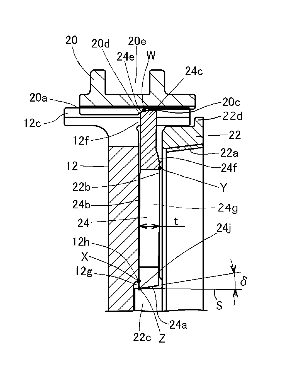
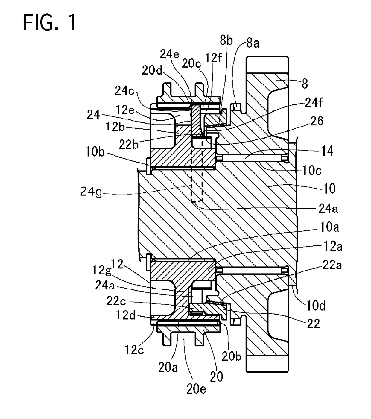
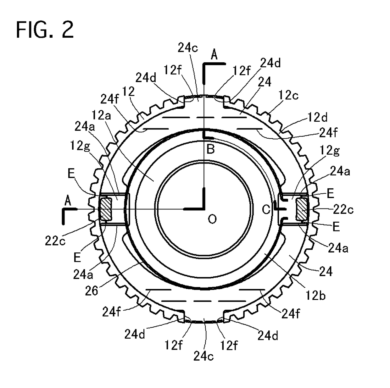
[0053]Referring to FIGS. 1 to 5 of the drawings, there is shown a first preferred embodiment of a shift device with a synchronizer according to the present invention, which is used for a transmission of a motor vehicle. In the first embodiment, the shift device is capable of being selectively shifted between a neutral position and a reverse position in the transmission.

[0054]The shift device includes an output shaft 10, a hub 12, a reverse-speed gear 8, a sleeve 20, a synchronizer ring 22, two lever members 24, and a spring 26.

[0055]The output shaft 10 is connected with a pair of drive wheels through a not-shown final unit having differential gears. The output shaft 10 is provided with outer splines 10a on an external surface of a left side portion thereof in FIG. 1. The outer splines 10a are engaged with inner splines formed on an inner surface of a boss portion 12a of the hub 12, and the hub 12 is restrained from moving in an axial direction, being sandwiched between a snap ring 1...

second embodiment

[0100]Next, a shift device of a second embodiment will be described with reference to drawings of FIGS. 6 to 18.

[0101]As shown in FIG. 6, the shift device of the second embodiment has a first speed gear 16 and a second speed gear 18, being rotatably supported on an output shaft 10 and a bush 10e through the bearings 14, at the both sides of a hub 12 in an axial direction, respectively. The bush 10e is fixed on the output shaft 10 at a left side of the output shaft 10 in FIG. 6. Two synchronizer rings 22 are respectively arranged at the both sides of the hub 12, namely at a first-speed-gear side and a second-speed-gear side of the hub 12, respectively, corresponding to the first speed gear 16 and the second speed gear 18.

[0102]The first speed gear 16 and the second speed gear 18 are always engaged with not-shown first speed drive gear and not-shown second speed drive gear, respectively, which are supported on a not-shown input shaft parallel to the output shaft 10.

[0103]The hub 12 is...

third embodiment

[0128]Next, a shift device of a third embodiment will be described with reference to a drawing of FIG. 19.

[0129]The shift device of the third embodiment is constructed similarly to that of the second embodiment except the configurations of lever members 24 and springs 26. That is, the torque receiving portions 24a of the lever members 24 of the third embodiment do not have the slanted surfaces with the angle δ of the second embodiment, and, instead of that, hub-side end portions of the press portions 26d of the springs 26 are bent to form a press surface 26f. Accordingly, the friction torque is transmitted from the projections 22c of the synchronizer ring 22 to the torque receiving portions 24a of the lever members 24 through the press surfaces 26f of the spring 26 during the synchronization operation.

[0130]As indicated by an arrow G in FIG. 19, the area of contact points of the press surfaces 26f and the torque receiving portions 24a corresponds to the thickness of a plate forming ...


PUM


Abstract

A shift device includes an output shaft, a hub, a speed gear, a sleeve, a synchronizer ring, lever members, and a spring. The lever members have torque receiving portions contactable with projections of the synchronizer ring to receive friction torque from the projections. Contact positions of the torque receiving portions and the projections in a synchronization operation are set at a hub side of the lever members and an axial-directional distance between points of support and the contact positions is less than a thickness of the lever member.

Description

BACKGROUND OF THE INVENTION[0001]1. Field of the Invention[0002]The present invention relates to a shift device with a synchronizer for a transmission of a motor vehicle and the like in which press force applied to a sleeve can be transmitted to a synchronizer ring under a leverage operation using lever members while gears of the transmission are shifted.[0003]2. Description of the Related Art[0004]Such a conventional shift device is disclosed in Japanese Patent No. 3,699,775. This conventional shift device is equipped with a plurality of lever members located among a hub, a sleeve, and a synchronizer ring, where the synchronizer ring is capable of being pressed toward the speed gear due to a leverage operation using the lever members. In addition, the lever members decrease gear noise in a reverse-shift operation in a 5-speed forward transmission.[0005]In any case of synchronization operations toward 5-speed and the reverse-speed, the lever members are pressed and moved toward outw...

Claims


Application Information

Patent Timeline
Patent Type & Authority Patents(United States)
IPC IPC(8): F16D23/06F16D23/02F16H55/17
CPCF16D23/06F16D23/025F16D2023/065F16D2023/0631F16D2023/0637F16H2055/178Y10T74/19284
Inventor HIRAIWA, KAZUYOSHI
Owner KYOWA METAL WORKS
Why Eureka
Try Eureka