Spinning Rotor for an Open-End Spinning Machine having a Friction-Enhancing Lining Made of an Elastomeric Material, and Open-End Spinning Machine

a technology of friction-enhancing lining and spinning rotor, which is applied in the direction of open-end spinning machines, continuous wounding machines, and paper mills. it can solve the problems of increased flexing work, wear and tear of the belt and the spinning rotor, and the rotor can only be accelerated very slowly or may never even reach the operating speed, so as to reduce the wear of improve the force transmission between the belt and the rotor sha

Inactive Publication Date: 2019-05-16
RIETER INGOLSTADT GMBH
View PDF10 Cites 0 Cited by
  • Summary
  • Abstract
  • Description
  • Claims
  • Application Information

AI Technical Summary

Benefits of technology

[0010]Moreover, it is advantageous when the lining has a lining thickness of at most 1 mm, preferably at most 0.75 mm and, particularly preferably, at most 0.5 mm. The flexing work in the rotor drive and, therefore, the energy consumption, can be further reduced as a result.
[0011]Moreover, it is advantageous when the at least one recess is designed as at least one circumferential groove. In the simplest variant, the circumferential groove can be designed as a rectangular groove in this case, into which the plastic material has been introduced, in particular, via vulcanization. The lining is subjected to only slight wear as a result. In this case, it is also advantageous when the lining thickness is at most 1 mm, preferably at most 0.75 mm and, particularly preferably, at most 0.5 mm. The depth of the recess can be limited as a result and a weakening of the spinning rotor, which would reduce its characteristic frequency and result in undesirable oscillations during operation, can be avoided as a result. In this embodiment as well, the lining can be continuously applied or in the form of interspaced strips or rings.
[0012]In order to provide a preferably smooth outer surface of the rotor shaft and, therefore, a preferably planar support surface for the belt, it is furthermore advantageous when the rotor shaft, including the introduced lining, is ground. As a result, the force transmission between the belt and the rotor shaft can be improved and wear of the belt and of the rotor shaft can be reduced.
[0013]It is particularly advantageous when the lining is made of nitrile rubber or of hydrogenated acrylonitrile butadiene rubber. This not only has the friction and damping properties which are favorable for the operation of the spinning rotor, but is also antistatic, and so trash deposits in the area of the lining can be avoided. A close fit of the belt on the rotor shaft and, therefore, good force transmission between the belt and the rotor are further enhanced as a result. It is also conceivable, however, that the lining is made of a polyurethane elastomer or a natural rubber. These also have a favorable friction coefficient with respect to the drive belt and therefore provide for an energy-saving and low-wear operation of the open-end spinning device.
[0014]It is also advantageous when the rotor shaft is made of a metal, in particular, an aluminum material or a steel material. The heat, which still forms in the lining due to the flexing work between the belt and the lining, can be dissipated in a particularly favorable way as a result.
[0015]Such a spinning rotor comprising a rotor shaft which is provided with a friction coefficient-increasing material in its contact area can be utilized particularly advantageously for the energy-saving and low-maintenance operation of an open-end spinning device. Therefore, protection for an open-end spinning device comprising such a spinning rotor is also claimed.

Problems solved by technology

Due to the slip between the belt and the rotor shaft, wear can occur on the belt as well as the spinning rotor, however, despite the pressure roller.
Due to a wear of the belt, however, there may nevertheless be an insufficient force transmission between the belt and the rotor shaft, and so the spinning rotors can only be accelerated very slowly or may never even reach their operating speed.
This results in increased flexing work in the lining of the support disks, which results in considerable energy consumption in the area of the rotor bearing.

Method used


Image

  • Spinning Rotor for an Open-End Spinning Machine having a Friction-Enhancing Lining Made of an Elastomeric Material, and Open-End Spinning Machine
  • Spinning Rotor for an Open-End Spinning Machine having a Friction-Enhancing Lining Made of an Elastomeric Material, and Open-End Spinning Machine

Examples


Embodiment Construction

[0021]Reference will now be made to embodiments of the invention, one or more examples of which are shown in the drawings. Each embodiment is provided by way of explanation of the invention, and not as a limitation of the invention. For example features illustrated or described as part of one embodiment can be combined with another embodiment to yield still another embodiment. It is intended that the present invention include these and other modifications and variations to the embodiments described herein.

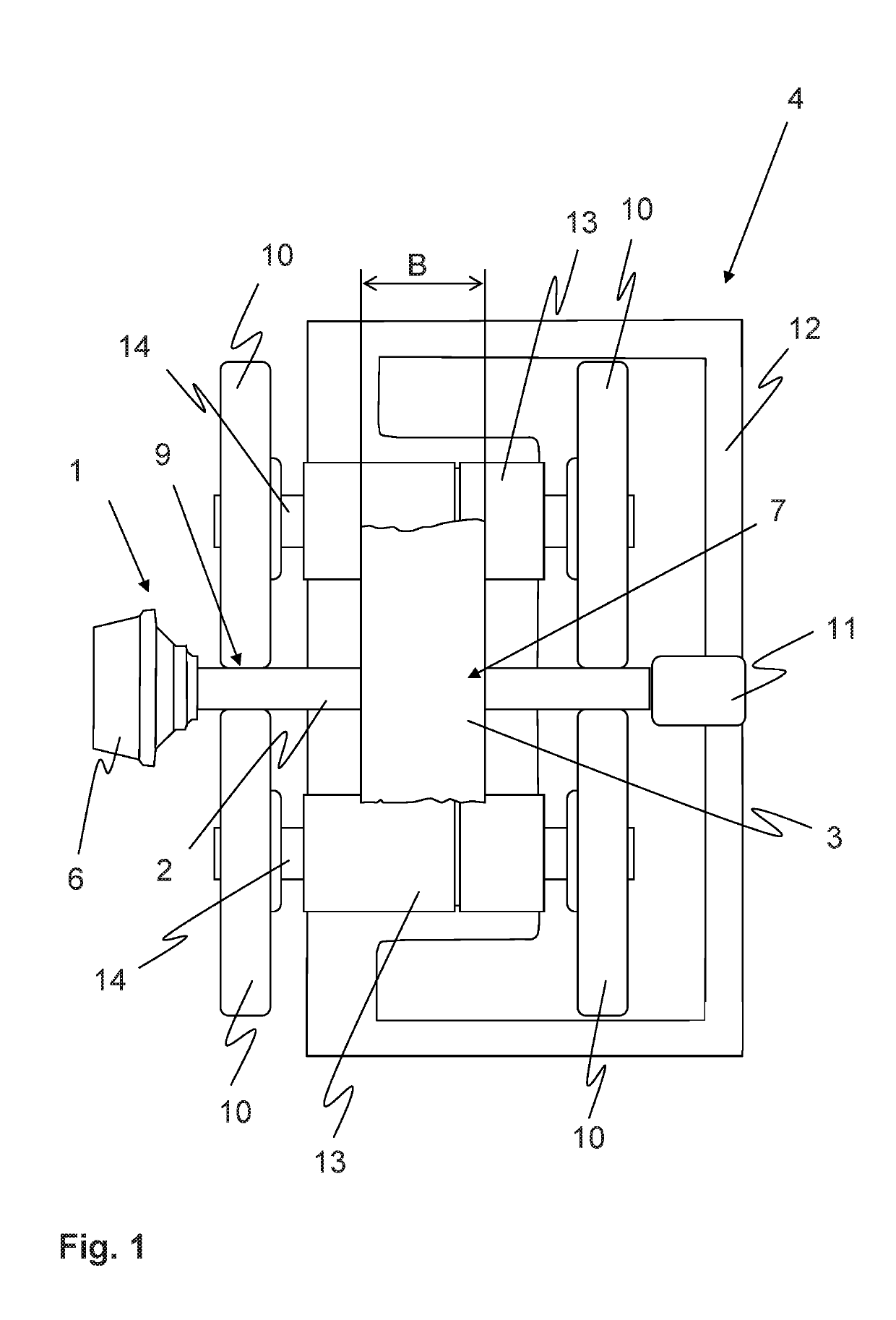
[0022]FIG. 1 shows a schematic top view of an open-end spinning device 4 comprising a spinning rotor 1 and a belt 3 for driving the spinning rotor 1. In this case, the spinning rotor 1 usually consists of the rotor shaft 2 and a rotor cup 6, which can be removably as well as fixedly connected to the rotor shaft 2. The spinning device 4 includes, in the usual way, a bearing device for the spinning rotor 1, which is designed in the form of a support disk bearing in this case. Two sup...


PUM

PropertyMeasurementUnit
thicknessaaaaaaaaaa
thicknessaaaaaaaaaa
thicknessaaaaaaaaaa

Abstract

A spinning rotor for an open-end spinning device includes a rotor shaft, via which the spinning rotor is driven with the aid of a belt. A contact area is on the rotor shaft for engagement with the belt. A friction coefficient-increasing lining made of an elastomeric material is applied along at least part of the contact area.

Description

FIELD OF THE INVENTION[0001]The present invention relates to a spinning rotor for an open-end spinning device, comprising a rotor shaft, via which the spinning rotor is driven with the aid of a belt, in particular, a tangential belt. The rotor shaft includes a contact area for the belt.BACKGROUND[0002]With respect to spinning rotors of open-end spinning machines, it has been common for a long time to drive these spinning rotors with the aid of a tangential belt which rests against the shaft of the spinning rotor. The spinning rotors are usually mounted on support disks in this case. The belt is generally pressed against the rotor shaft in this case with the aid of an additional drive roller in order to reduce the slip between the belt and the rotor shaft. In this case, it can also be provided to change the contact pressure of the pressure roller in order, for example, to provide for a faster ramp-up of the spinning rotors or to enable an adaptation to different spinning materials or...

Claims


Application Information

Patent Timeline
Patent Type & Authority Applications(United States)
IPC IPC(8): D01H4/12D01H4/10D01H1/241
CPCD01H4/12D01H4/10D01H1/241
Inventor GREIS, DIETMAR
Owner RIETER INGOLSTADT GMBH
Why Eureka
Try Eureka