

Overvoltage Clamp With Parallel Controlled Resistive Path
- Summary
- Abstract
- Description
- Claims
- Application Information
AI Technical Summary
Benefits of technology
Problems solved by technology
Method used
Image

Examples
Embodiment Construction
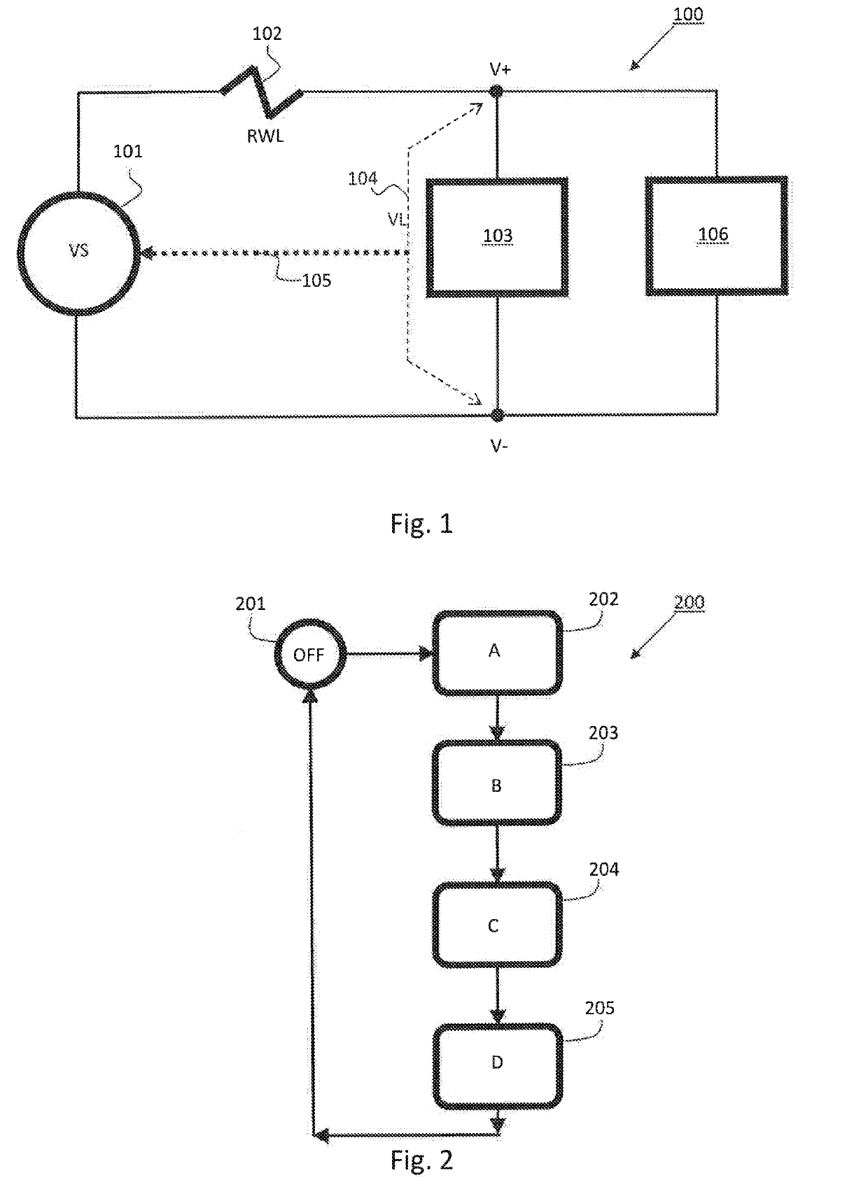
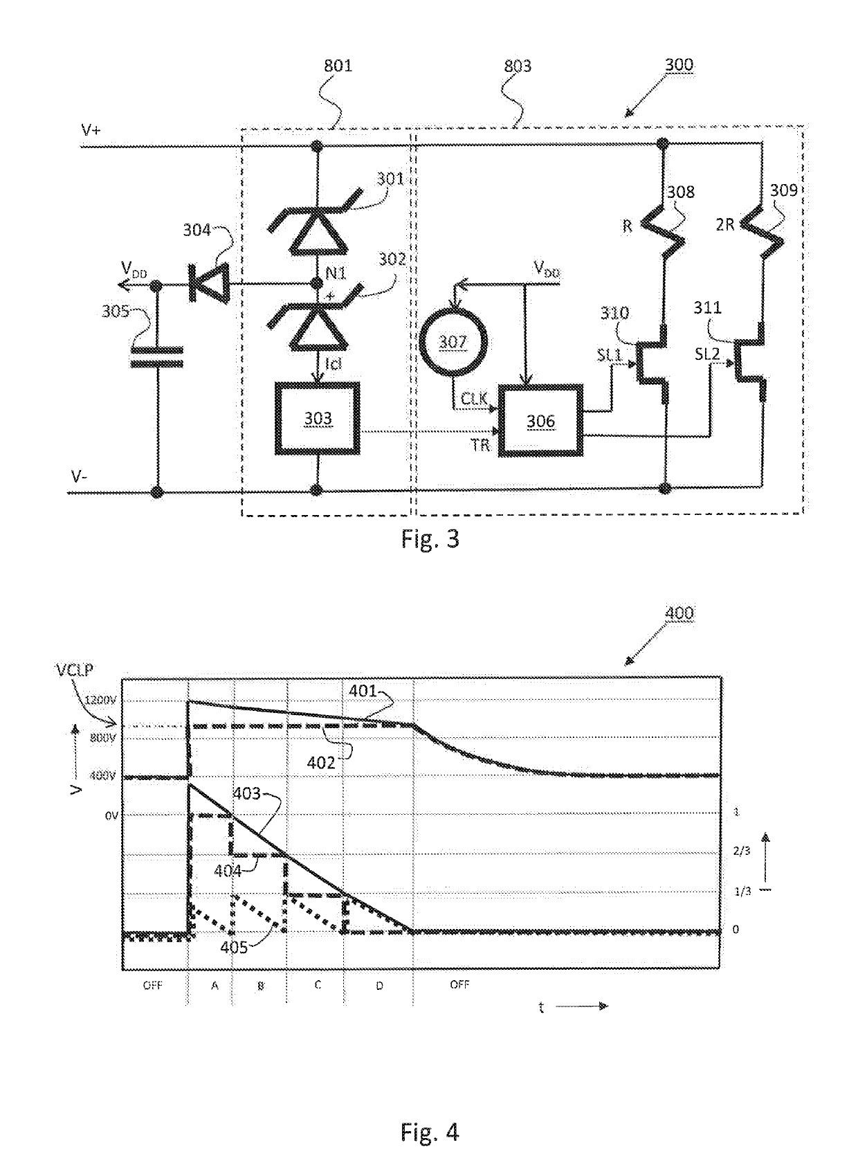
[0052]The essence of the present invention is an overvoltage protection circuit that prevents the voltages applied to it from exceeding a predetermined level. FIG. 1 shows a block diagram of an electrical power supply system 100, where the present invention may be utilized, as earlier discussed. FIG. 2 shows a flowchart 200 of the operation of an embodiment of the overvoltage protection circuit as shown in FIG. 3. FIG. 3 shows a block diagram of an embodiment of the overvoltage protection circuit 300 in accordance with the invention.
[0053]With reference to FIG. 3, the overvoltage protection circuit 300 comprises two terminals connected to said terminals V+, V− for clamping the voltage over said terminals. The circuit 300 comprises a series connection of a first Zener diode 301, a second Zener diode 302 and a current sensor / detector 303 between said terminals V+, V−. An intermediate node N1 in between said Zener diodes is connected to a capacitor 305 via a diode 304 as illustrated. T...
PUM
 Abstract
Description
Claims
Application Information