
Systems and methods for medical monitoring

Active Publication Date: 2019-05-30
NEOPENDA PBC
View PDF4 Cites 11 Cited by
  • Summary
  • Abstract
  • Description
  • Claims
  • Application Information

AI Technical Summary

Benefits of technology

The present patent relates to medical devices and methods for obtaining patient-specific biometric data in real-time. The medical device may include a temperature sensor and an optical sensor, and a microcontroller may be configured to calculate various biometric data such as body temperature, pulse rate, respiratory rate, and blood oxygen concentration based on the received temperature and optical signals. The device may also include a display for displaying the biometric data. The patent also describes a medical system that includes multiple wearable medical devices positioned on different patients, with each device including a temperature and optical sensor. The system may also include a user device or server for receiving and processing the biometric data. The technical effects of the patent include improved accuracy and efficiency in monitoring patient health and providing personalized care.

Problems solved by technology

Many hospitals and medical care providers have insufficient resources, are understaffed, and / or are overwhelmed with patients.
Hospitals and medical care providers in many developing countries, for example, often lack sufficient equipment, skilled technicians, and stable power supplies.
As such, hospitals and medical care providers in many developing countries often experience disproportionally high neonatal mortality rates.
Often times, however, insufficient equipment, time, and / or an inconsistent power supply reduces the medical professional's ability to continuously and reliably monitor the vital signs for each patient.

Method used


Image

  • Systems and methods for medical monitoring
  • Systems and methods for medical monitoring
  • Systems and methods for medical monitoring

Examples


case 50

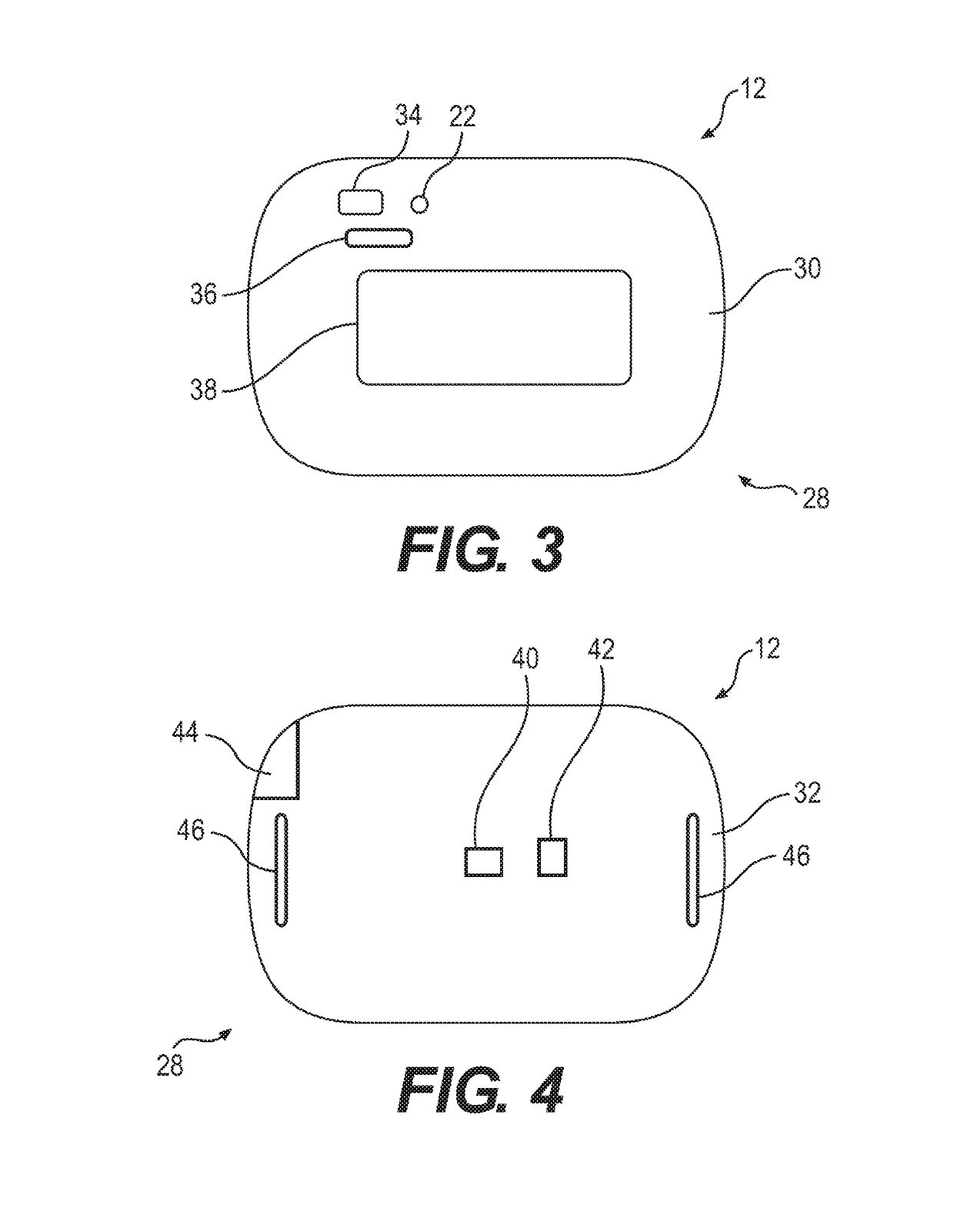
[0048]Back case 50 may include slots 46 to attach strap 26 to housing 28. Front case 48 and back case 50 may enclose a plurality of internal components 52 positioned between front portion 30 and back portion 32. Internal components 52 may include a battery 54 and a printed circuit board 56. Printed circuit board 56 may include a microcontroller and / or processor, a transmitter unit, a receiver unit, an antenna, and other electrical components to transmit signals to, and receive signals from indicator 22, battery level indicator 36, display 38, temperature sensor 40, optical sensor 42, and charging port 44. Printed circuit board 56 and the electrical components may be powered by battery 54. In one aspect, battery 54 may be a 3.7 V battery with a 700 mAh capacity, 450 mAh charge current, and a 14 mAh discharge current. Battery 54 may have a charge time of approximately 105 minutes and a runtime of approximately 50 hours. In one aspect, battery 54 may be rechargeable and may run for mul...


PUM


Abstract

A medical device includes a temperature sensor configured to deliver a temperature signal and an optical sensor configured to deliver an optical signal. The medical device also includes a microcontroller configured to receive the temperature signal and the optical signal. The microcontroller is configured to calculate, in real-time, a body temperature, a pulse rate, a respiratory rate, and a blood oxygen concentration based on the received temperature signal and the received optical signal. The medical device also includes a display configured to display the body temperature, the pulse rate, the respiratory rate, and the blood oxygen concentration of a patient.

Description

TECHNICAL FIELD[0001]Various aspects of the present disclosure relate generally to systems and methods useful in monitoring one or more patients.BACKGROUND OF THE DISCLOSURE[0002]Many hospitals and medical care providers have insufficient resources, are understaffed, and / or are overwhelmed with patients. Hospitals and medical care providers in many developing countries, for example, often lack sufficient equipment, skilled technicians, and stable power supplies. As such, hospitals and medical care providers in many developing countries often experience disproportionally high neonatal mortality rates. In some aspects, mortality rates may be reduced if care is provided at a first indication of distress, such as, e.g., one or more abnormal vital signs of a patient. Often times, however, insufficient equipment, time, and / or an inconsistent power supply reduces the medical professional's ability to continuously and reliably monitor the vital signs for each patient. Therefore, health issu...

Claims


Application Information

Patent Timeline
IPC IPC(8): A61B5/00A61B5/01A61B5/0205A61B5/1455G08B21/04G08B21/18
CPCA61B5/746A61B5/01A61B5/02055A61B5/14551A61B5/0008A61B5/02427A61B5/7475A61B5/743A61B5/7425G08B21/0453G08B21/182A61B5/6804A61B5/6831A61B5/74A61B5/747A61B5/0022A61B5/02416A61B5/02438A61B5/0816A61B5/6814A61B5/725A61B5/7257A61B5/7278G16H40/67A61B2560/0214
Inventor SHAH, SONACAUVEL, TERESAPEYSER, REBECCA
Owner NEOPENDA PBC
Learn More