Vehicle speed control

a technology for controlling the speed of vehicles and vehicles, applied in the direction of control devices, vehicle components, external condition input parameters, etc., can solve the problems of ineffective control systems of vehicles, set to be automatically disabled, and ineffective systems in certain driving conditions, so as to increase driver confidence, enhance vehicle composure, and increase the effect of view

Active Publication Date: 2019-05-30
JAGUAR LAND ROVER LTD
View PDF0 Cites 7 Cited by
  • Summary
  • Abstract
  • Description
  • Claims
  • Application Information

AI Technical Summary

Benefits of technology

[0019]Embodiments of the invention have the advantage that the control system may adjust the speed of travel of the vehicle when approaching a crest of a slope in order to enhance vehicle composure and increase driver confidence during a given driving experience.
[0069]The control system may be configured to cause vehicle speed to begin to reduce to the predetermined crest speed value when the vehicle is at a control location, the control location being a distance ahead of the predetermined speed location which is dependent on an amount of rolling resistance experienced by the vehicle. The rolling resistance in this case is an amount of drag caused by the road surface upon which the vehicle is driving. Where the rolling resistance (drag) is relatively high, the control location may be a relatively short distance ahead of the predetermined speed location, whereas where the rolling resistance is relatively low, the control location may be a relatively long distance ahead of the predetermined speed location.

Problems solved by technology

In congested traffic conditions, however, where vehicle speed tends to vary widely, cruise control systems are ineffective, and especially where the systems are inoperable because of a minimum speed requirement.
Such systems are therefore ineffective in certain driving conditions (e.g. low speed) and are set to be automatically disabled in circumstances in which a user may not consider it to be desirable to do so.
Accordingly, they are not well suited to maintaining vehicle progress when driving in off road conditions where such events may be relatively common.

Method used


Image

  • Vehicle speed control
  • Vehicle speed control
  • Vehicle speed control

Examples


Embodiment Construction

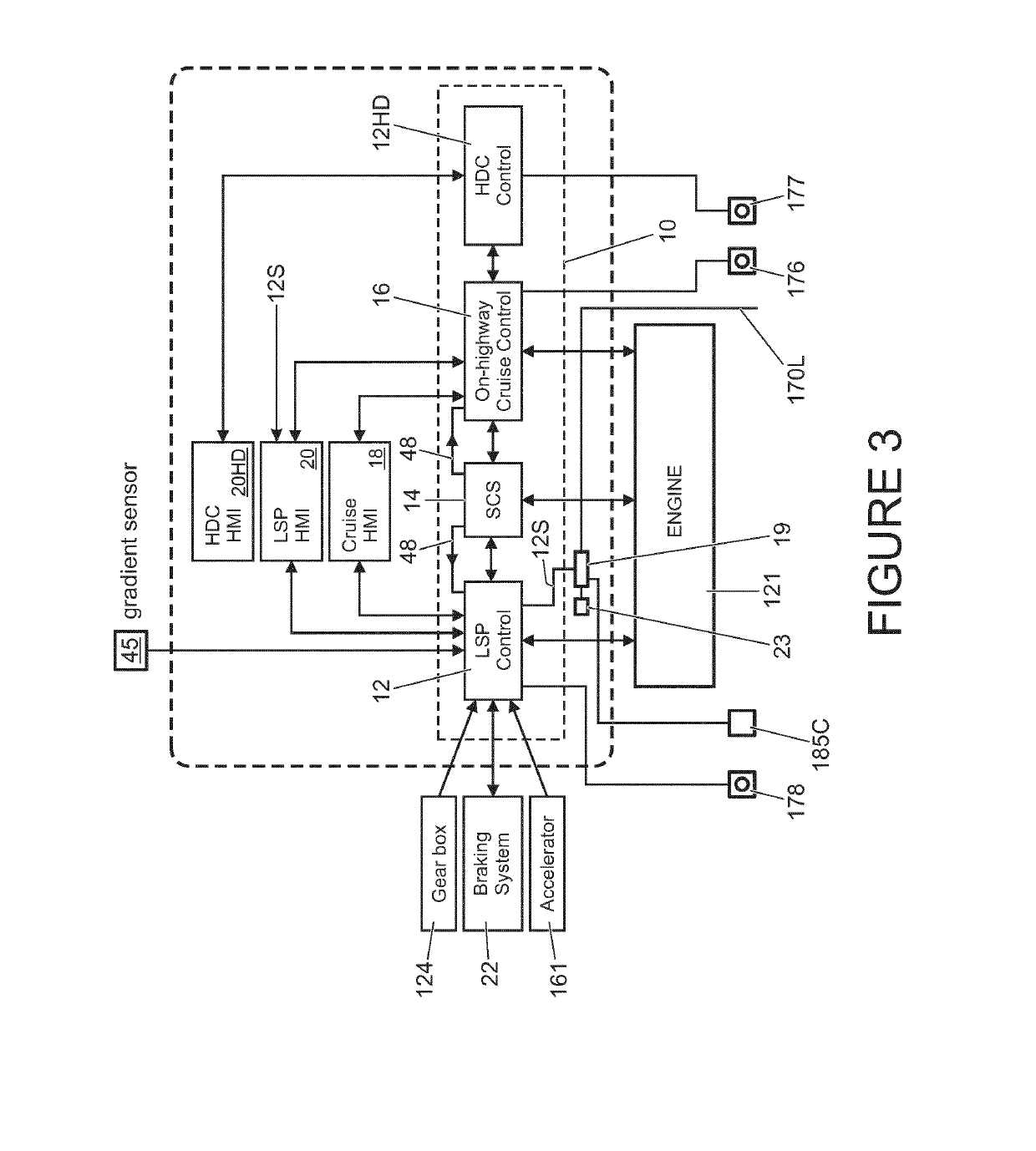
[0087]References herein to a block such as a function block are to be understood to include reference to software code for performing the function or action specified which may be an output that is provided responsive to one or more inputs. The code may be in the form of a software routine or function called by a main computer program, or may be code forming part of a flow of code not being a separate routine or function. Reference to function block is made for ease of explanation of the manner of operation of embodiments of the present invention.

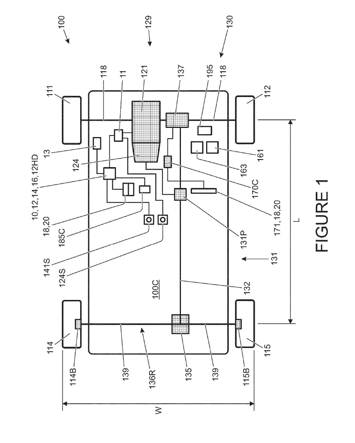
[0088]FIG. 1 shows a vehicle 100 according to an embodiment of the present invention. The vehicle 100 has a powertrain 129 that includes an engine 121 that is connected to a driveline 130 having an automatic transmission 124. It is to be understood that embodiments of the present invention are also suitable for use in vehicles with manual transmissions, continuously variable transmissions or any other suitable transmission.

[0089]In the embo...


PUM


Abstract

A speed control system (12) for a vehicle (100), the speed control system (12) being configured to: automatically cause application of positive and negative torque, as required, to one or more wheels of a vehicle (100) to cause a vehicle to travel in accordance with a target speed value, the target speed value being stored in a memory of the control system (12); and detect a crest of a slope ahead of the vehicle (100); wherein the speed control system (12) is configured automatically to attempt to adjust a speed of the vehicle (100) to cause the vehicle (100) to travel at a predetermined crest speed value when a crest of a slope is detected ahead of the vehicle (100), the predetermined crest speed value being determined in dependence at least in part on terrain gradient information respect of terrain prior to the crest.

Description

INCORPORATION BY REFERENCE[0001]The content of co-pending UK patent applications GB2507622 and GB2499461 are hereby incorporated by reference. The content of U.S. Pat. No. 7,349,776 and co-pending international patent applications WO2013124321 and WO2014 / 139875 are incorporated herein by reference. The content of UK patent applications GB2492748, GB2492655 and GB2499279 and UK patent GB2508464 are also incorporated herein by reference.FIELD OF THE INVENTION[0002]The invention relates to a system for controlling the speed of a vehicle. In particular, but not exclusively, the invention relates to a system for controlling the speed of a land-based vehicle which is capable of driving in a variety of different and extreme terrains and conditions.BACKGROUND[0003]In known vehicle speed control systems, typically referred to as cruise control systems, the vehicle speed is maintained on-road once set by the user without further intervention by the user so as to improve the driving experience...

Claims


Application Information

Patent Timeline
Patent Type & Authority Applications(United States)
IPC IPC(8): B60W30/14B60W10/184B60W10/22B60W10/06B60W10/10B60W50/00
CPCB60W30/143B60W50/0097B60W10/06B60W10/10B60W10/184B60W10/22B60W2420/42B60W2550/142B60W2550/143B60W2720/103B60K2310/244B60W2720/10B60W2552/20B60W2552/15B60T8/1755B60W10/20B60W30/146
Inventor FAIRGRIEVE, ANDREW
Owner JAGUAR LAND ROVER LTD
Why Eureka
Try Eureka