Rotor lamination and motor having the same

a technology of rotor lamination and motor, applied in the direction of dynamo-electric machines, magnetic circuit shape/form/construction, structural associations, etc., can solve the problems of increasing the difficulty of the manufacturing process of motors, reducing the torque capacity of motors,

Active Publication Date: 2019-05-30
UBTECH ROBOTICS CORP LTD
View PDF0 Cites 0 Cited by
  • Summary
  • Abstract
  • Description
  • Claims
  • Application Information

AI Technical Summary

Problems solved by technology

One problem with these methods is that they tend to lead to a reduction in motor torque capability and increase the difficulty of the manufacturing process of motors.

Method used


Image

  • Rotor lamination and motor having the same
  • Rotor lamination and motor having the same
  • Rotor lamination and motor having the same

Examples


Embodiment Construction

[0015]The disclosure is illustrated by way of example and not by way of limitation in the figures of the accompanying drawings, in which like reference numerals indicate similar elements. It should be noted that references to “an” or “one” embodiment in this disclosure are not necessarily to the same embodiment, and such references can mean “at least one” embodiment.

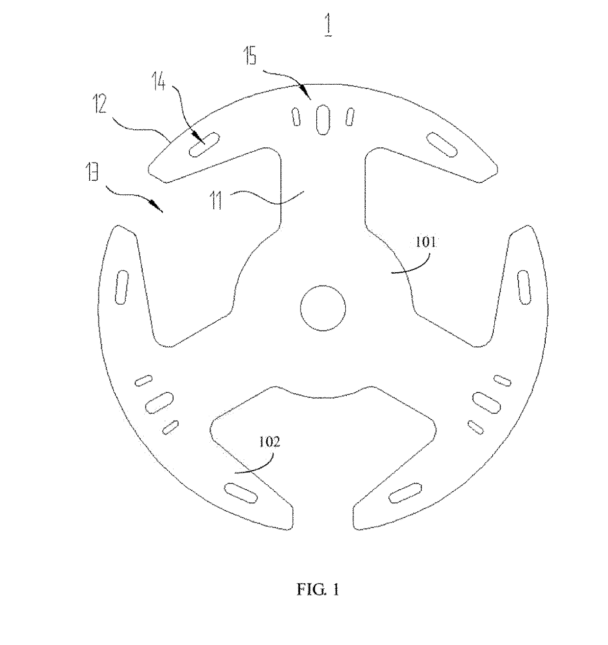
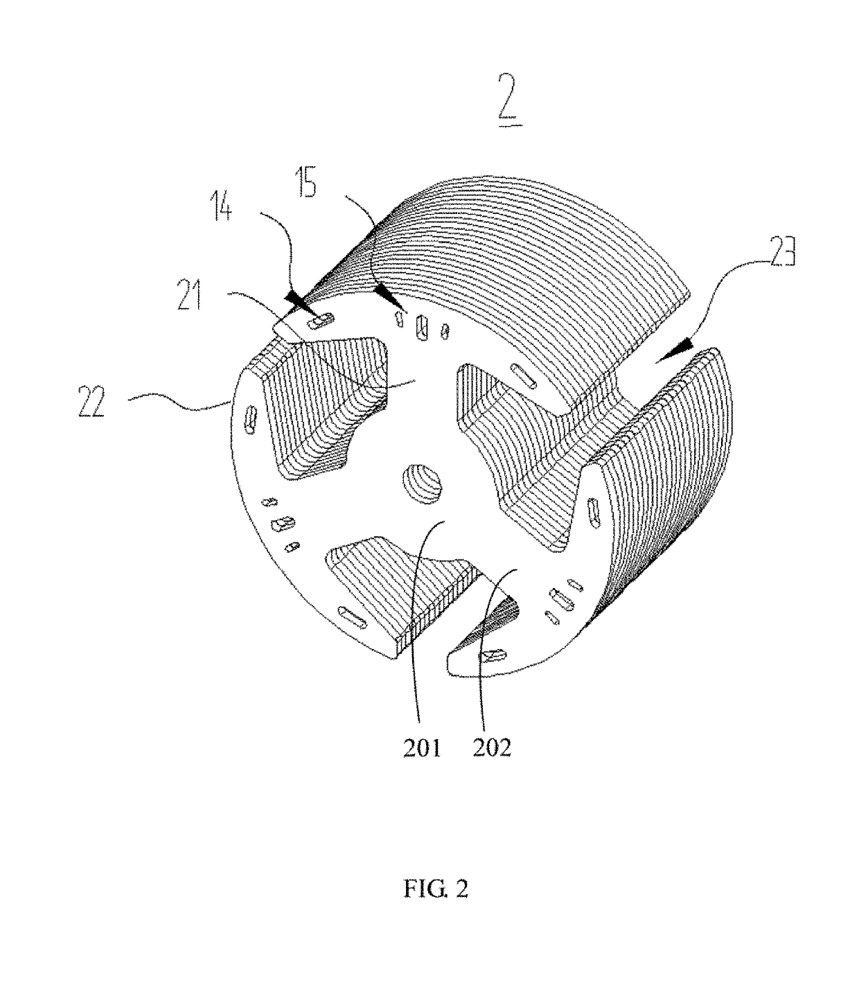
[0016]FIGS. 1 and 2 show an inner rotor lamination 1 for a PMDC motor according to one embodiment. A rotor core 2 is formed by stacking a number of the laminations 1 together. The lamination 1 includes a circular yoke 101 and a number of teeth 102 connected to the yoke. Each of the teeth 102 includes a tooth body 11 connected to the yoke and a tooth tip 12 connected to a distal end of the tooth body 11. A winding slot 13 is formed between each two adjacent tooth bodies 11. At least one tooth tip 12 defines one or more first through holes 15 adjacent to a radial end thereof, and one or more second through holes 14. Each o...


PUM


Abstract

An inner rotor lamination for a permanent magnet direct current motor includes a yoke and a plurality of teeth connected to the yoke. Each of the teeth has a tooth body connected to the yoke and a tooth tip connected to a distal end of the tooth body. A winding slot is formed between each two adjacent tooth bodies. One tooth tip defines one or more first through holes adjacent to a radial end thereof, and one or more second through holes. Each of the one or more second through holes is located adjacent to one circumferential end of the at least one tooth tip.

Description

CROSS REFERENCE TO RELATED APPLICATIONS[0001]This application claims priority to Chinese Patent Application No. 201711213150.0, filed Nov. 28, 2017, which is hereby incorporated by reference herein as if set forth in its entirety.BACKGROUND1. Technical Field[0002]The present disclosure generally relates to motors, and particularly to a rotor lamination for a permanent magnet direct current (PMDC) motor and a PMDC motor.2. Description of Related Art[0003]Electromagnetic noise is one of the main sources of motor noise. It is generated because electromagnetic force acting in the air gap between the stator and the rotor generates a rotating force wave or a pulse dynamic wave, which acts on the stator to generate vibration. The electromagnetic noise is related to the harmonic magnetic field in the air gap of the motor and the amplitude and frequency of the electromagnetic force and number of poles, as well as the vibration characteristics of the stator itself. For permanent magnet DC mot...

Claims


Application Information

Patent Timeline
Patent Type & Authority Applications(United States)
IPC IPC(8): H02K1/22
CPCH02K1/223H02K29/03H02K2201/03H02K2213/03H02K1/08H02K1/146H02K1/16H02K1/24H02K1/26H02K11/012
Inventor XIONG, YOUJUNZHOU, YANLI, YOUPENGFAN, WENHUA
Owner UBTECH ROBOTICS CORP LTD
Why Eureka
Try Eureka