Device for Aseptically Connecting Large Bore Tubing

a technology of aseptic shielding and connectors, which is applied in the direction of flanged joints, pipe joints, couplings, etc., can solve the problems of frequent undesired or not permitted, high cost of antibiotics, and inability to use such methods, so as to improve the performance of flanged tubing connectors, improve the resistance to joint rupture or deformation, and improve the effect of performan

Active Publication Date: 2019-06-06
SHEVITZ JERRY
View PDF0 Cites 6 Cited by
  • Summary
  • Abstract
  • Description
  • Claims
  • Application Information

AI Technical Summary

Benefits of technology

[0050]The invention is a flanged tubing connector enhanced with a protective shield covering its central channel. That connector can be joined to an identical or similar connector so that fluid can, in sterile fashion, flow from one piece of tubing, through both connectors, into a second piece of tubing. The design improves performance when large-bore tubing is being joined. One reason is that the rivets or bolts that connect opposing flanges in joined connectors are placed as far from the flange periphery or as close to the connected conduit and sealing gasket as reasonably possible—making the joined connectors more resistant to joint rupture or to deformation due to high fluid pressures.
[0051]In contrast to previous designs, each connector comprises an ample recess for storage of the protective shield thereby avoiding the necessity of dragging the shield across a tight-fitting abrasive flange surface while the shield is being removed from the joined connectors. Furthermore the shields are fitted with half of a T-shaped pull grip (combinable with the half from the joined connector) that accommodates all five fingers and the palm of a person's hand, allowing one to use nearly the full force of one's hand. The T-shaped pull grip makes it easier to pull the shield away from two joined connectors, a process that requires both breaking shield-to-flange adhesive bonds and pulling the shield through O-rings that are under compression forces. A protective cap with a compartment for internally storing the half pull grip is provided.

Problems solved by technology

The use of such methods; however, is fraught with problems.
Antibiotics are expensive and frequently undesired or not permitted in a particular process.
Bactericidal agents, can also be toxic or may contaminate the process.
The use of a flame to sterilize equipment was used routinely in the past but is no longer permissible because it creates a fire hazard.
A biological safety hood, although an effective place to work, is a fixture and frequently not accessible at the work site.
Such components can be very costly.
Therefore, a steam sterilization capability is typically limited to large facilities.
However, not all components used in processing are resistant to heat sterilization; e.g., probes, sensors, single-use vessels, and accessories.
Without the development of new technology, smaller companies would typically not have the resources or facilities to produce products for testing and trials.
However, even large companies found it difficult and costly to expand facilities on the basis of previous technologies.
However, those connectors are not well-suited for tubes with an inner diameter of 1.5 inches or more.

Method used


Image

  • Device for Aseptically Connecting Large Bore Tubing
  • Device for Aseptically Connecting Large Bore Tubing
  • Device for Aseptically Connecting Large Bore Tubing

Examples


Embodiment Construction

Terminology and Structure

[0052]The terminology is best understood initially by referring to the structures illustrated in the drawings. (Not all structures that contribute to the invention are discussed in this section.)

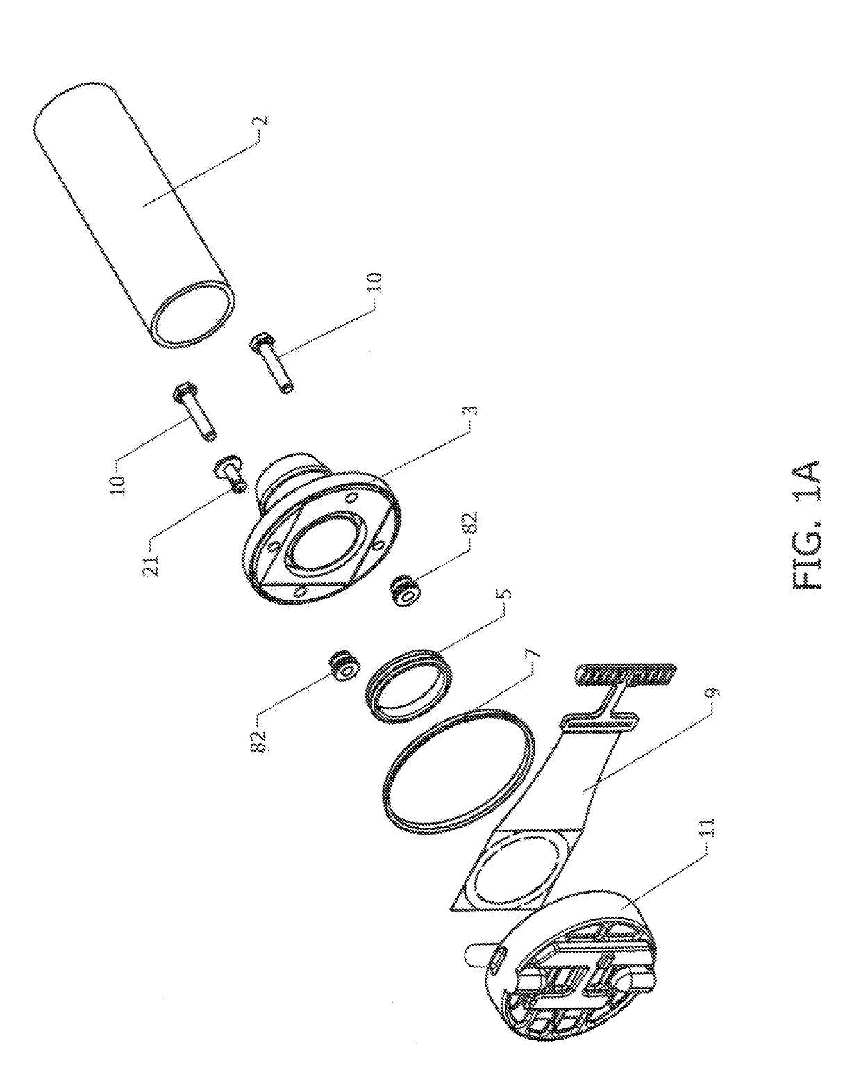
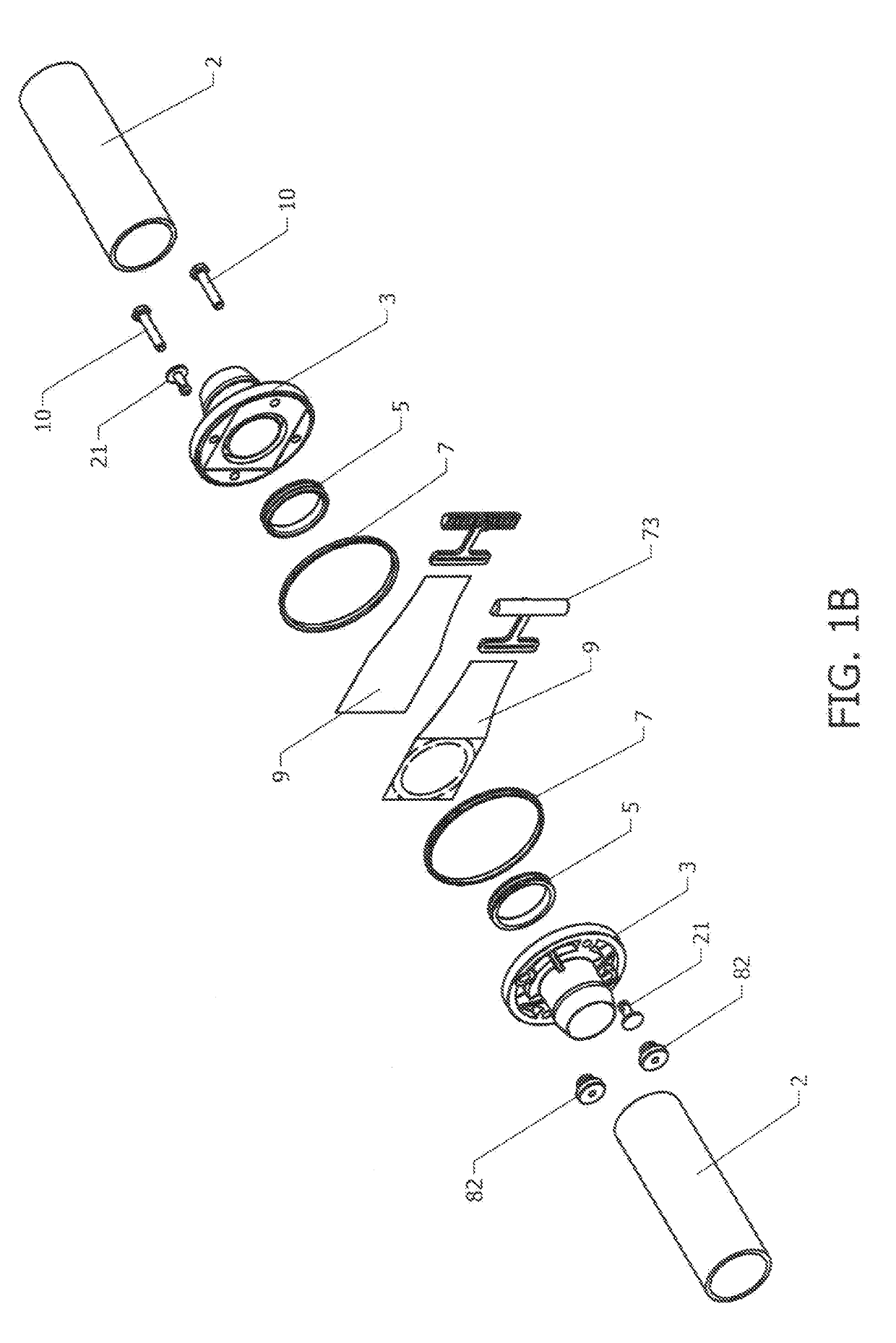
[0053]Three major structures of the connector 3, shown in FIGS. 3C and 3D, are a connector tube 46 that forms the flow conduit; a hose barb 4 at one end of the tube 46; and a flange 14 at the other end of that tube. Also shown in the figures is a hose barb tube connector, although other tube connectors may be used, e.g., the sanitary “I” line type connector. The features of the flange 14 are described in greater detail below: The “proximal” end (defined by the connector tube proximal rim 40) of the connector tube is the end of the connector tube that is closest to the flange and indeed often encircled by the flange. The other end of the connector tube is the “distal” end 85. The proximal and distal ends of the connector tube are references for the use of the terms pr...


PUM


Abstract

A connector for facilitating the connection of one piece of tubing to another so that fluid can flow from one piece to the other in a sterile manner. Characteristics of the connector include, hut are not limited to, a flange at one of the connector, the flange comprising a recess for storage of at least part of a protective shield which Is removable after the flange is connected to the flange of a second connector.

Description

CROSS REFERENCE TO RELATED APPLICATIONS[0001]This application claims the benefit of U.S. provisional application No. 62 / 344,079 filed Jun. 1, 2016, which application is incorporated by reference in its entirety herein.FIELD OF THE INVENTION[0002]The field of the invention is aseptically shielded connector devices that can be joined in an aseptic manner and used to join tubing that conveys fluid from one place to another.BACKGROUND OF THE INVENTION[0003]In processing biological materials, there is frequently a need to move large volumes of fluids efficiently and at reasonably low shear rates so as not to damage frail, high value products. Increasing the inner diameter of the tubing is a way to achieve those goals. The current invention is designed to address these objectives.[0004]The means for making aseptic connections between tubings is to some extent well understood and well developed. In the past such connections may have involved treating the connecting ends with a bactericidal...

Claims


Application Information

Patent Timeline
Patent Type & Authority Applications(United States)
IPC IPC(8): A61M39/18A61M39/12
CPCA61M39/18A61M39/12F16L23/024F16L29/007F16L2201/44A61M39/10F16L23/02
Inventor SHEVITZ, JERRY
Owner SHEVITZ JERRY
Why Eureka
Try Eureka