
Method and system to provide a generalized framework for dynamic creation of module analytic applications

a module analytic and general framework technology, applied in the direction of source code creation, program code transformation, instrumentation, etc., can solve the problems of limiting the use of such modules to the specific use case and class, difficult to reuse modules in a different application, and difficult to use any given module in a new application contex

Active Publication Date: 2019-06-06
BOOZ ALLEN HAMILTON INC
View PDF7 Cites 6 Cited by
  • Summary
  • Abstract
  • Description
  • Claims
  • Application Information

AI Technical Summary

Benefits of technology

The patent describes a method and system for creating an application flow logic, which is a combination of software tools that perform specific functions. The method involves parsing an application file into module descriptors, which are then used to create a module by accessing existing tools and combining them with other tools. The resulting application flow logic can be executed by accessing and using the produced modules in a computer memory device. The technical effect is a more efficient and streamlined process for creating complex software applications.

Problems solved by technology

Such designs ultimately limit the use of such modules to the specific use case and class (e.g., to a manager class, employee class, directory class) for which they were created.
As a consequence, it can be difficult to reuse modules in a different application once they have been developed in this manner.
This compelled interrelationship between modules makes it difficult to use any given module in a new application context, because the module has been designed to operate under the expectation or requirement that certain variables or data flows exist, which may not be true in the new application (for instance, requiring specific data as an argument to pass unaltered to another following module, or the expectation that another module will have modified some variable in some way prior to the module being called).
Built-in dependencies of this manner, which are common in object-oriented programming, ultimately limit the portability of the software code used to represent the module.

Method used


Image

  • Method and system to provide a generalized framework for dynamic creation of module analytic applications
  • Method and system to provide a generalized framework for dynamic creation of module analytic applications
  • Method and system to provide a generalized framework for dynamic creation of module analytic applications

Examples


Embodiment Construction

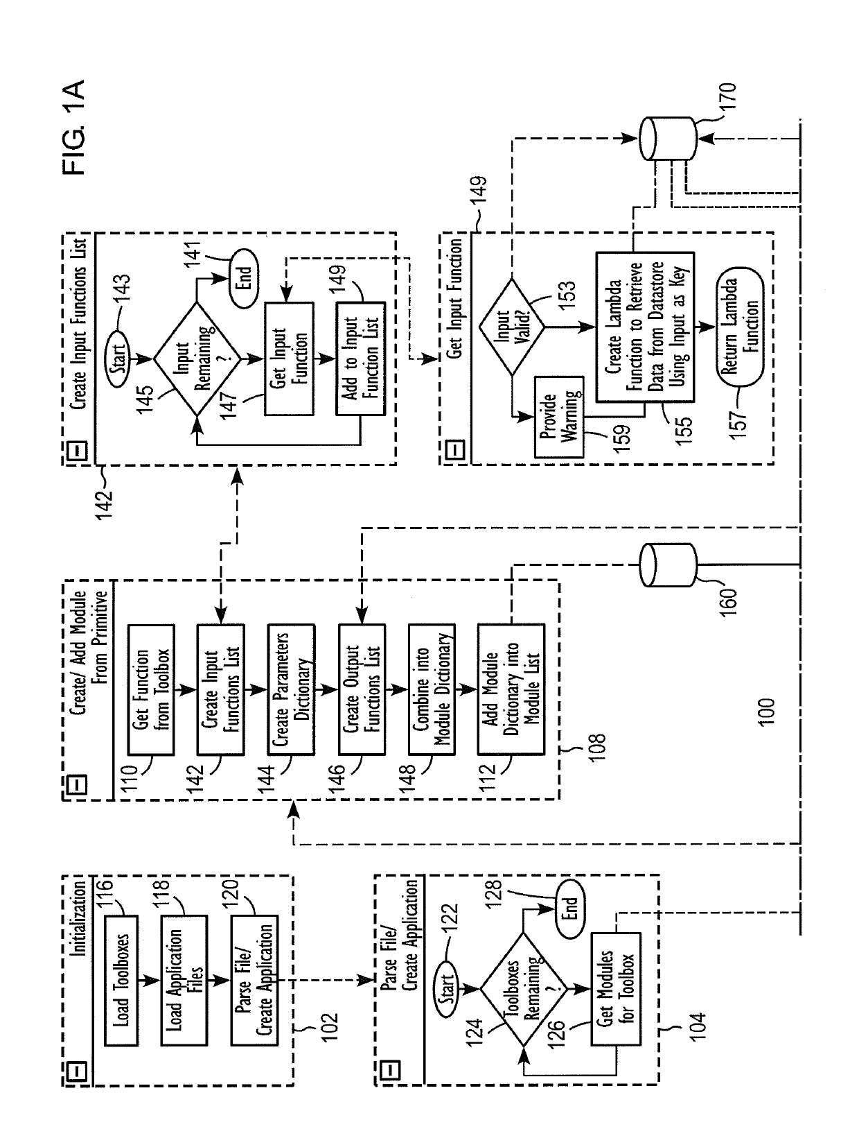
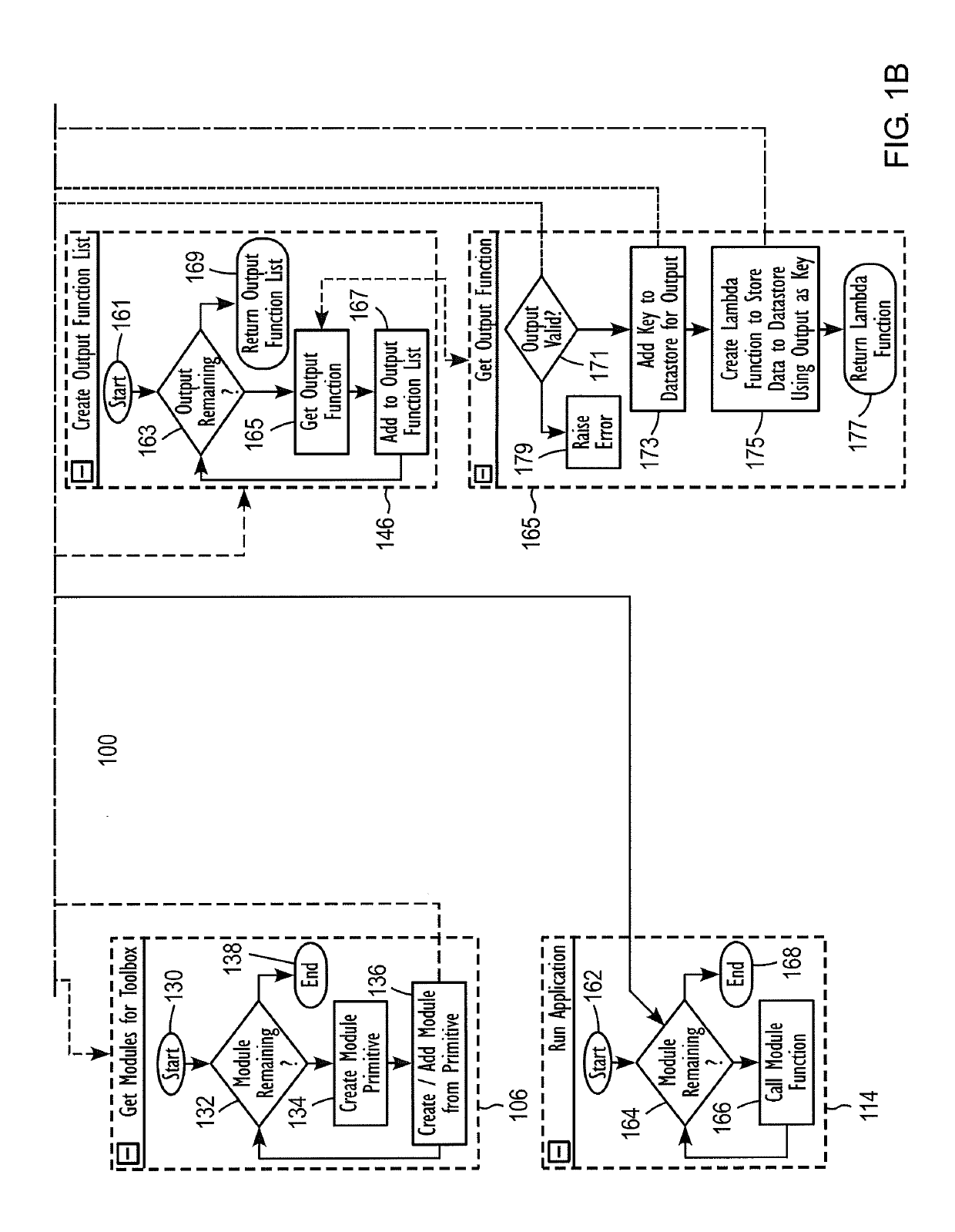
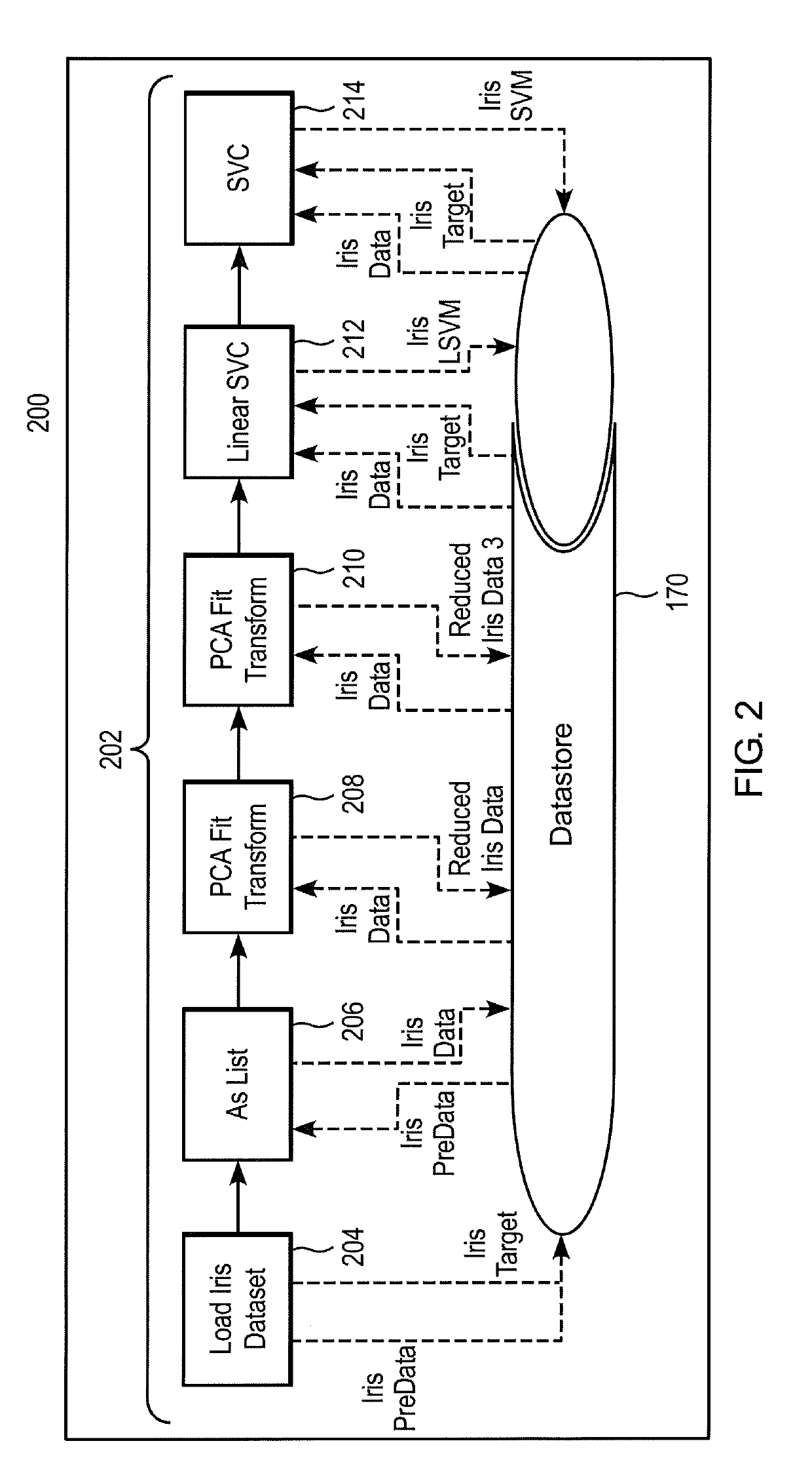
[0016]The present disclosure is directed to a method and system for providing a generalized framework for dynamic creation of module analytic applications. Exemplary embodiments as described herein provide a module structure for a software tool, and provide a software tool / datastore interface, which together allow for efficient application flow logic design and efficient end program execution, using for example, an input / output (I / O) wrapper function that is applied as “decorator” to abstract away intermodular dependencies from the modulas and thereby render a software tool / datastore interface transparent to a software tool, as disclosed herein. The software tools are fully portable for use in designing, developing and executing other new software applications that can be similarly executed with a high level of efficiency. Such software applications can be implemented by creating and accessing software tools that each have an input(s) which are only produced as the output(s) of anot...


PUM


Abstract

A method and apparatus for generating an application flow logic are disclosed which include performing an initialization process based on storage of at least one software toolbox in a toolbox list of a computer memory device; parsing an application description into a series of module descriptors; creating a module primitive defined in a dictionary as a data string representing a name of a tool in the software toolbox, and a data string for least one of: an input, an output, or a data string; producing a module for each module primitive, an input to each tool being produced as an output of another tool; assembling an application flow logic as a combination of produced modules; and providing access to the application flow logic for execution as a combination of calls to the produced modules stored in the computer memory device.

Description

RELATED APPLICATION[0001]This application claims priority under 35 U.S.C. § 119 to U.S. Provisional Application No. 62 / 594,265 filed Dec. 4, 2017, the entire content of which is hereby incorporated by reference in its entirety.FIELD[0002]The present disclosure is directed to a method and system for generating an application flow logic.BACKGROUND INFORMATION[0003]In developing and coding software associated with an application flow logic, software engineers often write modules for use in a specific software application. The modules represent functions to be performed and are developed to include data dependencies on other modules so as to facilitate the flow of data within the application. The modules, as a consequence of these dependencies, are therefore restricted to the specific program or to a limited set of programs that involve the same collection of modules and data flows.[0004]For example, in object-oriented programming, modules encapsulate functionality so as to facilitate p...

Claims


Application Information

Patent Timeline
Patent Type & Authority Applications(United States)
IPC IPC(8): G06F8/41
CPCG06F8/433G06F8/443G06F8/30G06F8/36
Inventor DEMPSEY, JAMES
Owner BOOZ ALLEN HAMILTON INC
Learn More