Bus attached compressed random access memory

a random access memory and bus technology, applied in the field of memory system for a computer, can solve the problems of software supporting the compression, complicating the operation system support and maintenance, and none of the references address solutions for ameliorating software overhead and extra-processing required in the current computer memory system, so as to simplify the operation system support and maintenance, and eliminate problems. , the effect of low cos

Inactive Publication Date: 2009-10-08
IBM CORP
View PDF25 Cites 134 Cited by
  • Summary
  • Abstract
  • Description
  • Claims
  • Application Information

AI Technical Summary

Benefits of technology

[0010]The present invention is directed to provide a system and method that eliminates problems (e.g., complicating an operating system support and maintenance), caused by a traditional compressed memory, by integrating a low cost memory, e.g., a flash memory device, in to the more expensive RAM. In addition, the present invention provides a memory controller to manage data exchange between a computer system (e.g., a CPU) and memory devices (e.g., DRAM, Flash memory). Moreover, the present invention eliminates the software and associated processing overhead necessary to manage data communication between a computer system (e.g., CPU) and memory devices (e.g., DRAM, Flash memory).

Problems solved by technology

However, when the data in a RAM does not compress as much as expected, then excess data needs to be handled by software, for example by writing the excess to a disk, deleting some data in the RAM, and so on.
The software for supporting the compression complicates an operating system support and maintenance.
None of these references address solutions for ameliorating software overhead and extra-processing required in current computer memory systems.

Method used


Image

  • Bus attached compressed random access memory
  • Bus attached compressed random access memory
  • Bus attached compressed random access memory

Examples


Embodiment Construction

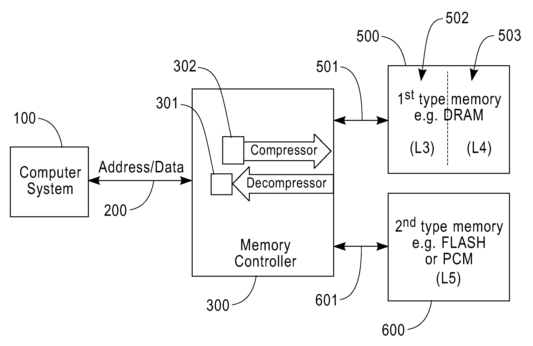
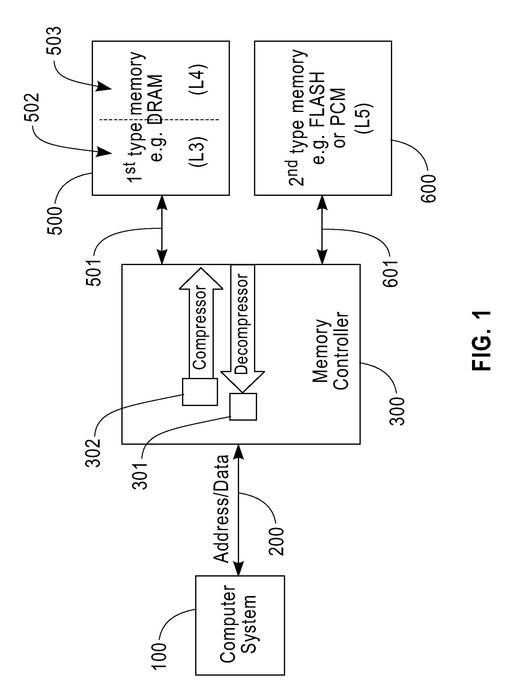
[0020]FIG. 1 depicts a block diagram depicting the memory system of the present invention. A computer system 100 such as a general purpose processor (e.g., IBM® Power-PC® Processor) communicates with a memory controller 300 via an address / data bus 200. The system further includes two memory storage devices, a first-type memory 500 having an uncompressed data region 502 (L3) and a compressed data region 503 (L4) and a second-type memory 600 (L5). In one embodiment, the first-type memory 500 is faster and more expensive than the second type memory 600. In this embodiment, the first-type memory 500 has less memory storage capacity than the second-type memory 600. The first-type memory 500 may be volatile memory such as Dynamic Random Access Memory (DRAM) and Static Random Access Memory (SRAM). The second-type memory 600 may be non-volatile memory such as NAND-based flash memory, NOR-based flash memory, Phase Change Memory (PCM), Ferroelectric RAM (FeRAM), and Magnetoresistive RAM (MRAM...


PUM


Abstract

A computer memory system having a three-level memory hierarchy structure is disclosed. The system includes a memory controller, a volatile memory, and a non-volatile memory. The volatile memory is divided into an uncompressed data region and a compressed data region.

Description

BACKGROUND OF THE INVENTION[0001]1. Fields of the Invention[0002]The present invention generally relates to a memory system for a computer. More particularly, the present invention relates to an improved system and method of controlling I / O access to a memory system for a computing device that includes a more cost-effective and more efficient multi-level (e.g., three-level) hierarchical memory structure comprising an uncompressed data region in a volatile memory, a compressed data region in the volatile memory, and a non-volatile memory.[0003]2. Description of the Prior Art[0004]In current computing system memory configurations, an effective size of a Random Access Memory (RAM) is doubled by implementing data compression. However, when the data in a RAM does not compress as much as expected, then excess data needs to be handled by software, for example by writing the excess to a disk, deleting some data in the RAM, and so on. The software for supporting the compression complicates a...

Claims


Application Information

Patent Timeline
Patent Type & Authority Applications(United States)
IPC IPC(8): G06F12/08
CPCG06F12/08G06F12/0897G06F2212/401G06F2212/2024G06F2212/2022
Inventor ABALI, BULENTKARIDIS, JOHN P.LASTRAS-MONTANO, LUIS A.
Owner IBM CORP
Why Eureka
Try Eureka