Electromagnetic Rotary Motor

a rotary motor and electromagnetic technology, applied in the direction of dynamo-electric machines, dc interrupters, structural associations, etc., can solve the problems of uneven motion and general inefficiency, many motors that utilize electromagnetic induction are inaccessible, and devices have not yet been optimized for general us

Active Publication Date: 2019-06-06
BLANKENSHIP MAXWELL JORDAN
View PDF0 Cites 1 Cited by
  • Summary
  • Abstract
  • Description
  • Claims
  • Application Information

AI Technical Summary

Benefits of technology

The present invention is an electromagnetic rotary motor that efficiently converts electrical energy into mechanical energy. It is designed to be used on small projects or items and is optimized for general use. The motor uses minimal electrical power input and has a high efficiency of energy conversion. It is also easy to use and maintain. The motor has a unique design that allows for the input of electrical charge through a rotor and the generation of magnetic fields to push or pull a magnet attached to the rotor, resulting in the rotation of the rotor. The motor is controlled by a set of brushes and electromagnetic mechanisms that react to the influence of the brushes. The motor is designed to be efficient, compact, and lightweight. The technical effects of the invention include a more efficient motor for converting electrical energy into mechanical energy and a simplified design for easy use and maintenance.

Problems solved by technology

Such devices, however, have not yet been optimized for general use.
These rotors tend to be heavy or sporting poor form factors, resulting in uneven motion and general inefficiency.
Many motors that utilize electromagnetic induction are inaccessible for usage on small projects or items.

Method used


Image

  • Electromagnetic Rotary Motor
  • Electromagnetic Rotary Motor
  • Electromagnetic Rotary Motor

Examples


Embodiment Construction

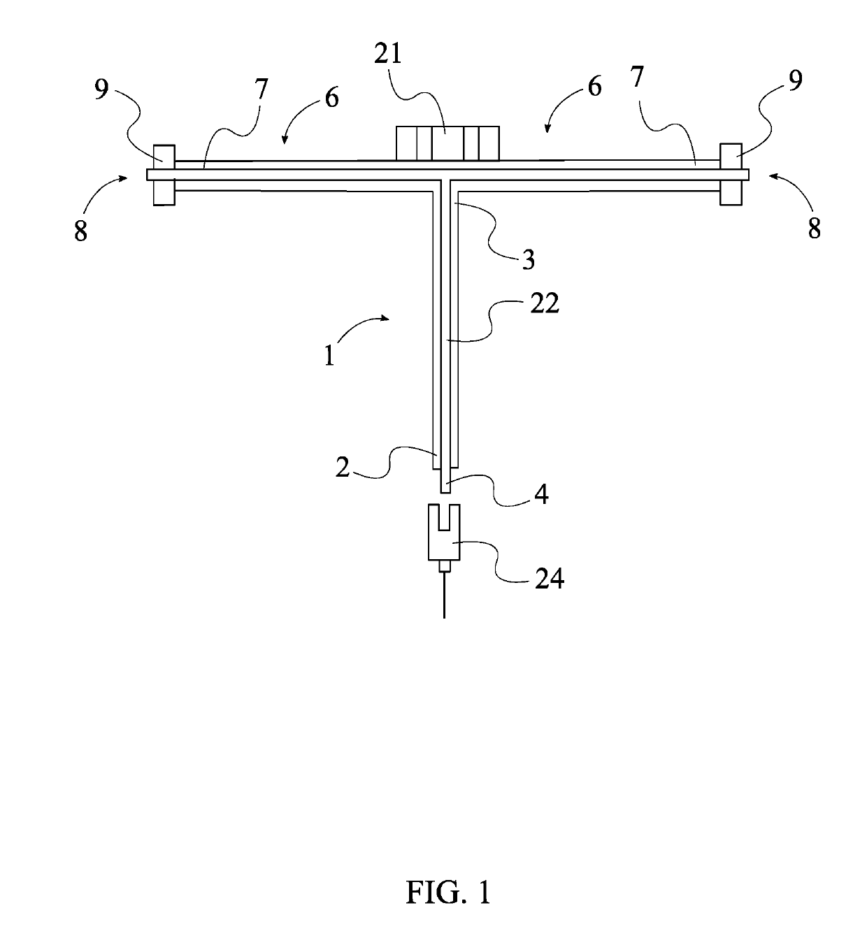
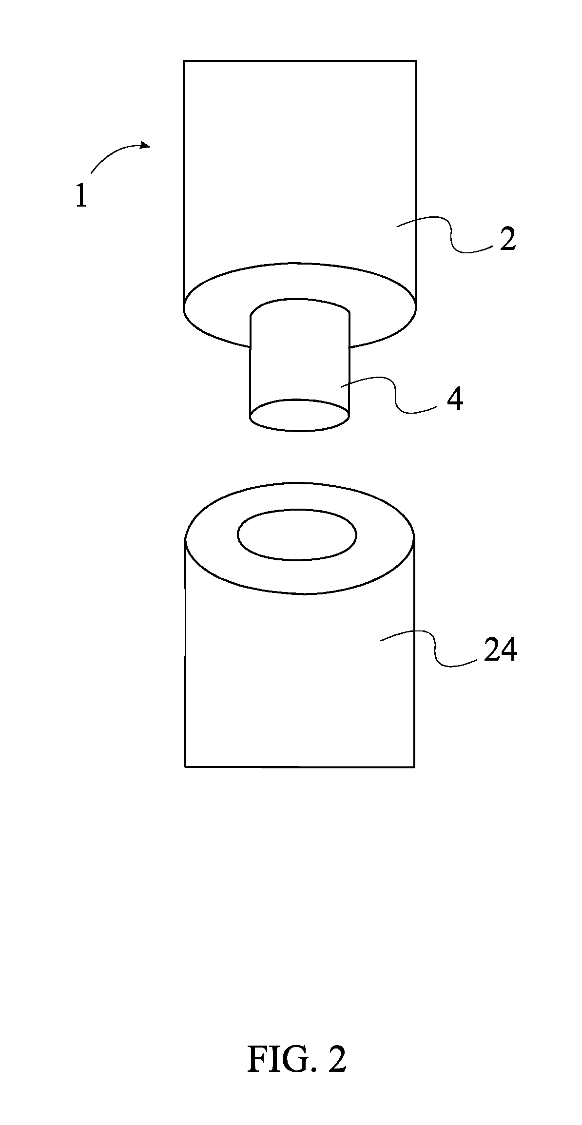
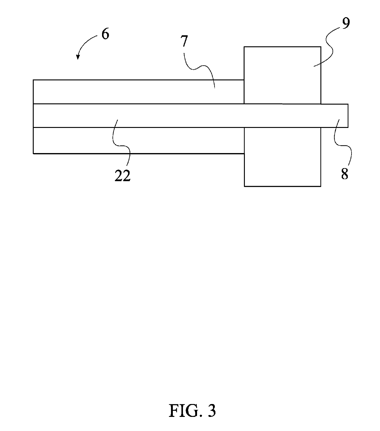
[0013]All illustrations of the drawings are for the purpose of describing selected versions of the present invention and are not intended to limit the scope of the present invention.

[0014]The present invention is an electromagnetic rotary motor that is used to convert electrical energy into mechanical energy. The present invention is also configured to utilize minimal electrical power input due to the arrangement of components and the cycle for energy conversion. The present invention comprises a drive shaft 1, an input terminal 4, an annular housing 5, a plurality of brushes 6, and a plurality of electromagnetic (EM) mechanisms 10. The drive shaft 1 is a cylindrical extrusion that rotates about its axis. The input terminal 4 is a connector which provides electrical potential to the plurality of brushes 6 through the drive shaft 1. The annular housing 5 is a ring-shaped enclosure that protects the components of the present invention and helps to arrange the plurality of EM mechanism...


PUM


Abstract

An electromagnetic rotary motor is an apparatus used to convert electrical energy into mechanical energy. The apparatus is also configured to utilize minimal electrical power input due to the arrangement of components and the cycle for energy conversion. The apparatus includes a drive shaft, an input terminal, an annular housing, a plurality of brushes, and a plurality of electromagnetic (EM) mechanisms. The drive shaft is a cylindrical extrusion that rotates about its axis. The input terminal is a connector which provides electrical potential to the plurality of brushes through the drive shaft. The annular housing is a ring-shaped enclosure that protects the components of the apparatus. The plurality of EM mechanisms is a set of electrical components that react to the influence of the plurality of brushes. The general configuration of the aforementioned components allows the apparatus to efficiently and effectively convert electrical energy into mechanical energy.

Description

[0001]The current application is a continuation-in-part (CIP) application of the U.S. non-provisional application Ser. No. 15 / 369,151 filed on Dec. 5, 2016.FIELD OF THE INVENTION[0002]The present invention generally relates to an energy conversion device. More specifically, the present invention is an electromagnetic rotary motor that utilizes induced magnetism to generate mechanical power.BACKGROUND OF THE INVENTION[0003]The relationship between electricity and magnetism has been explored through countless experiments, and several theories and equations have been developed to explore their interaction. The discovery that electricity could create magnetic fields, which could in turn create electrical currents, was among the greatest scientific breakthroughs of the past century. Following that discovery, induced electricity and magnetism have contributed to the skyrocketing of electronics production. Development of precision in controlling these principles has further resulted in an ...

Claims


Application Information

Patent Timeline
IPC IPC(8): H02K13/12H02K5/22H02K7/116H02K11/21H02K11/30H02K11/40
CPCH02K13/12H02K5/225H02K7/116H02K11/21H02K11/30H02K11/40H02K25/00
Inventor BLANKENSHIP, MAXWELL JORDAN
Owner BLANKENSHIP MAXWELL JORDAN
Why Eureka
Try Eureka