Eureka AIR delivers breakthrough ideas for toughest innovation challenges, trusted by R&D personnel around the world.

Pot gripper and cooking system comprising the pot gripper and a pot

a technology of pot gripper and cooking system, which is applied in the field of pot gripper, can solve the problems of cumbersome removal of cookware from the pot after preparing food, increased risk of cookware falling from the burner, and inability to easily attach the pot gripper to the support portion, so as to facilitate the separation of the pot gripper from the pot, prevent the movement of the pot relative to the pot gripper, and facilitate the effect of pot gripper stabilization

Active Publication Date: 2019-06-13
PRIMUS AB
View PDF6 Cites 5 Cited by
  • Summary
  • Abstract
  • Description
  • Claims
  • Application Information

AI Technical Summary

Benefits of technology

The invention is a cooking system with a pot gripper and a pot. The pot gripper has two levers that are locked in the closed position, preventing the pot from being separated accidentally. The pot has a gripping area at the open side of the pot with a larger diameter, which makes it safe to attach the pot gripper. This invention improves safety and efficiency in cooking.

Problems solved by technology

While placing the cookware on the burner is normally possible, removing the cookware therefrom after preparing the food is cumbersome without a handle, as the cookware distinctly heated up and cannot be gripped with bare hands.
However, in case the cook is not careful when placing the cookware on the burner without the pot gripper, it might happen that the support portion is, e.g., hidden behind the windshield and the cook cannot easily attach the pot gripper to the support portion after the food has been prepared.
This is cumbersome and the risk that the cookware is dropped from the burner is distinctly increased.
In addition, there is the drawback that the known pot grippers are sometimes not firmly attached to the support portion, so that the cookware may inadvertently be released from the pot gripper and drop on the floor.
As a matter of course, the food prepared will be lost in such a case.

Method used


Image

  • Pot gripper and cooking system comprising the pot gripper and a pot
  • Pot gripper and cooking system comprising the pot gripper and a pot
  • Pot gripper and cooking system comprising the pot gripper and a pot

Examples


Embodiment Construction

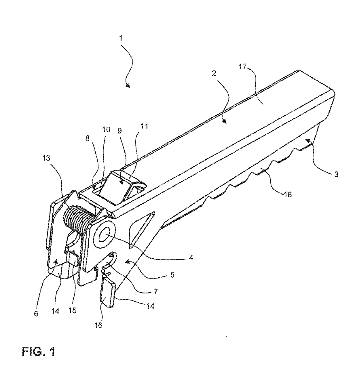
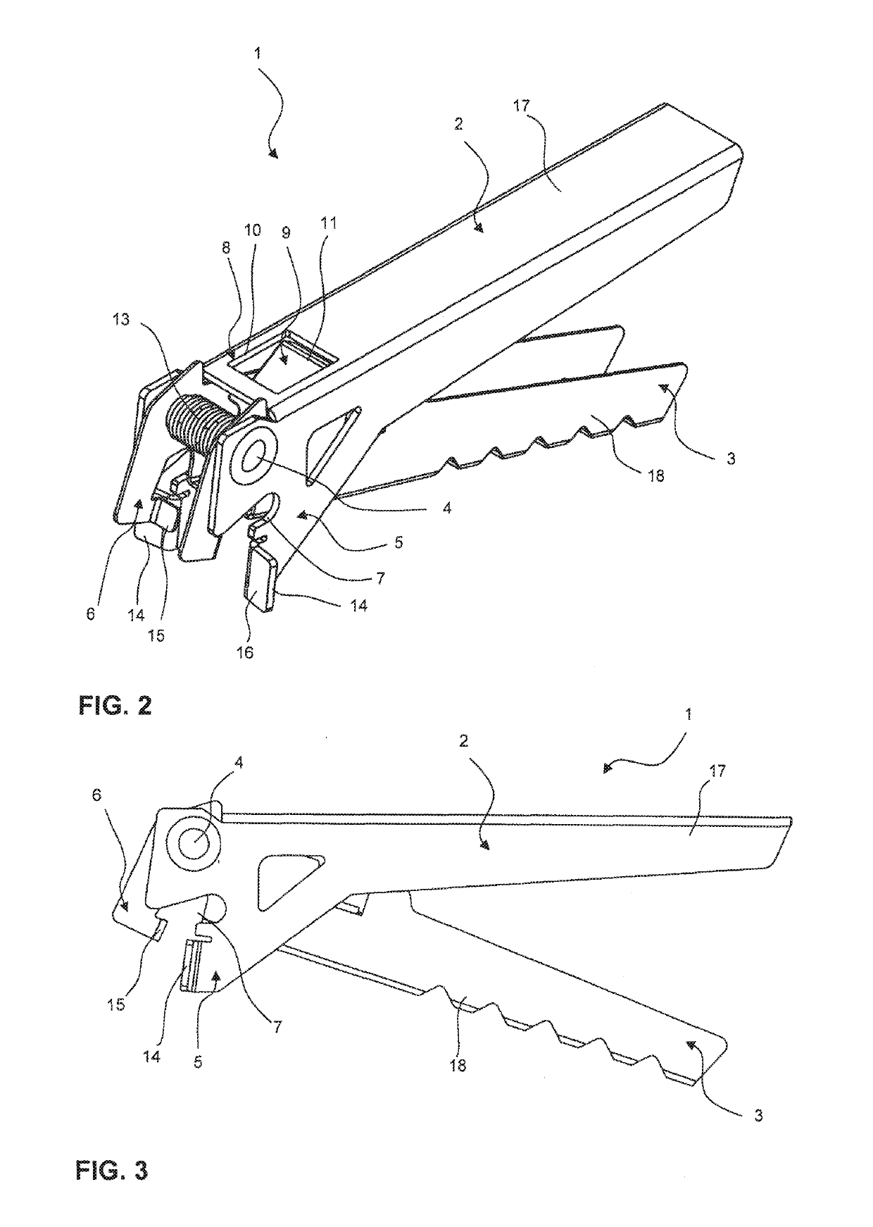
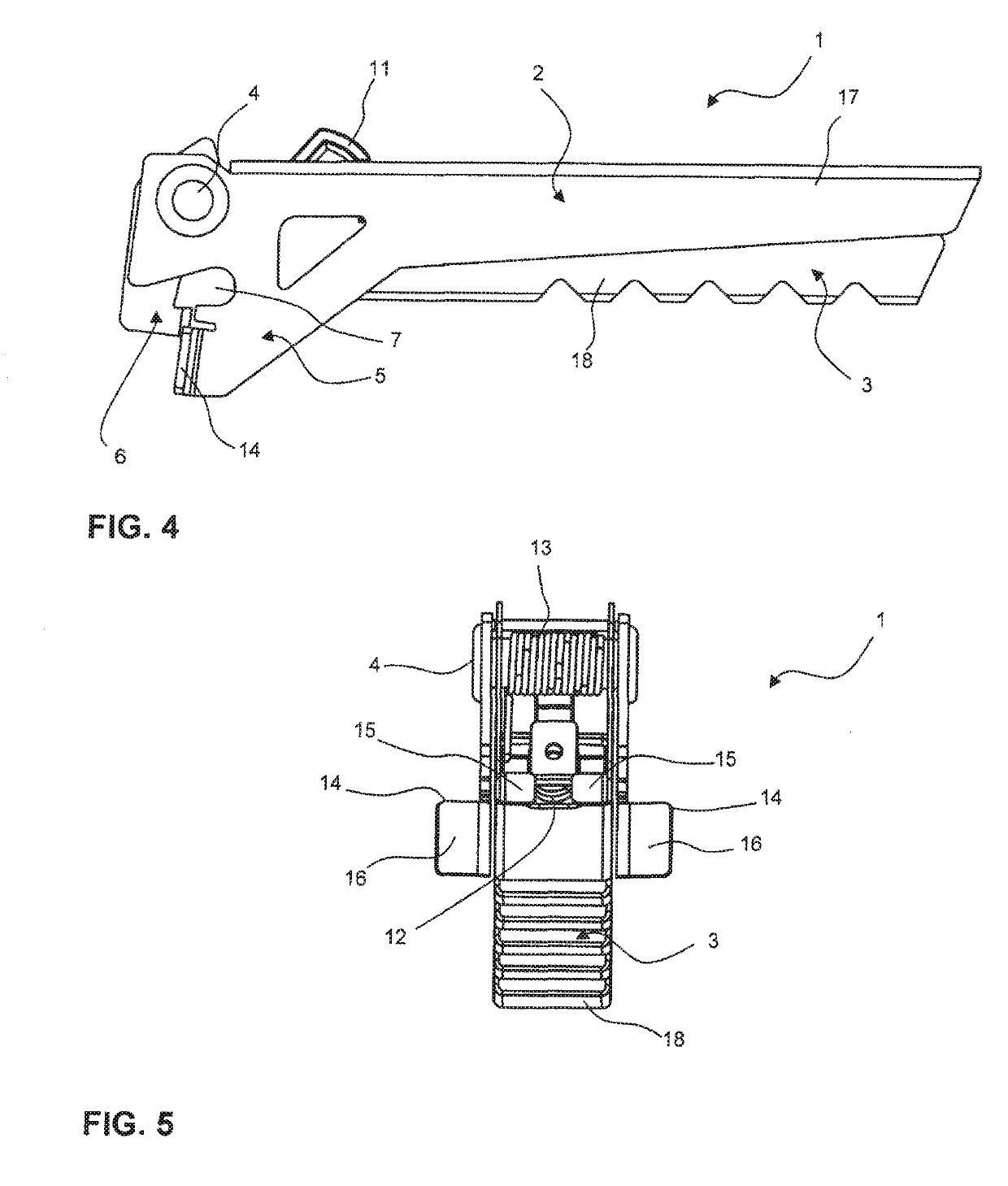
[0028]As shown in the figures, the pot gripper 1 comprises a first lever 2 and a second lever 3, The first lever 2 and the second lever 3 are joined by a fulcrum 4. In this embodiment, the fulcrum 4 is an axle. The first lever 2 has a first jaw 5 extending from the fulcrum 4 to one side and a first handle 17 extending from the fulcrum 4 to the other side. The second lever 3 has a second jaw 6 extending from the fulcrum 4 to one side and a second handle 18 extending from the fulcrum 4 to the other side. The pot gripper 1 can be rotated between an open position OP and a closed position CP in that the first handle 17 and the second handle 18 are rotated about the fulcrum 4. In the closed position, the first jaw 5 and the second jaw 6 define a clamping area for a pot (not shown).

[0029]As can be seen, e.g., in FIG. 1, the first jaw 5 comprises a support slot 7 on each side of the first jaw 5. Each support slot 7 is shaped so that it matches the outer contour of the pot to be gripped by t...


PUM


Abstract

A pot gripper comprises a first lever and a second lever joined at a fulcrum. The first lever has a first jaw extending from the fulcrum and the second lever has a second jaw extending from the fulcrum. The first jaw and the second jaw define a clamping area for a pot when the first lever and the second lever are rotated from an open position into a closed position. The first jaw has at least one support slot, the support slot being shaped to fit to the contour of a gripping area of the pot to be held in the clamping area. The first lever has a first locking means and the second lever has a second locking means. The first locking means engages with the second locking means in the closed position, so that the first lever and the second lever are locked in the closed position.

Description

CROSS-REFERENCE TO RELATED APPLICATIONS[0001]This application is a national phase entry under 35 U.S.C. § 371 of International Patent Application PCT / EP2017 / 061025, filed May 9, 2017, designating the United States of America and published in English as International Patent Publication WO 2017 / 194521 A1 on Nov. 16, 2017, which claims the benefit under Article 8 of the Patent Cooperation Treaty to German Patent Application Serial No. 10 2016 207 933.6, filed May 9, 2016.TECHNICAL FIELD[0002]This disclosure relates to a pot gripper. In general, a pot gripper comprises a first lever and a second lever being joined at a fulcrum. The first lever has a first jaw extending from the fulcrum and the second lever has a second jaw extending from the fulcrum. The first jaw and the second jaw define a clamping area for a pot when the first lever and second lever are rotated from an open position into a closed position. Further, the disclosure relates to a cooking system comprising the pot gripper...

Claims


Application Information

Patent Timeline
Patent Type & Authority Applications(United States)
IPC IPC(8): A47J45/10B25B7/02B25B7/14
CPCA47J45/10B25B7/02B25B7/14
Inventor LILLJEDAHL, NIKLASSVARTSTROM, ERIC
Owner PRIMUS AB
Why Eureka
Eureka Blog
Learn More