Display control apparatus and control method for the same

a control apparatus and display technology, applied in the direction of color television details, television system details, television systems, etc., can solve the problems of difficult focus with the viewfinder (vf) or small attached monitor

Active Publication Date: 2019-06-13
CANON KK
View PDF5 Cites 5 Cited by
  • Summary
  • Abstract
  • Description
  • Claims
  • Application Information

AI Technical Summary

Benefits of technology

[0004]In one embodiment of the present invention, a display control apparatus capable of more favorably changing an enlarging area and setting a focus measurement area at the time of enlarged display, a control method for the display control apparatus, a computer program and a memory medium are provided,

Problems solved by technology

There is a problem with recent video cameras in that it is difficult to focus with the viewfinder (VF) or small attached monitor at the time of shooting in high resolution such as 4K shooting or 8K shooting.
Thus, the enlarging area cannot be changed to view the surrounding situation with the place for checking the focus state fixed on a specific object, Furthermore, it is also conceivable that after changing the enlarging area with the place for checking the focus state fixed on a specific object, the user might want to change the place for checking the focus state.

Method used


Image

  • Display control apparatus and control method for the same
  • Display control apparatus and control method for the same
  • Display control apparatus and control method for the same

Examples


first embodiment

Hardware Configuration

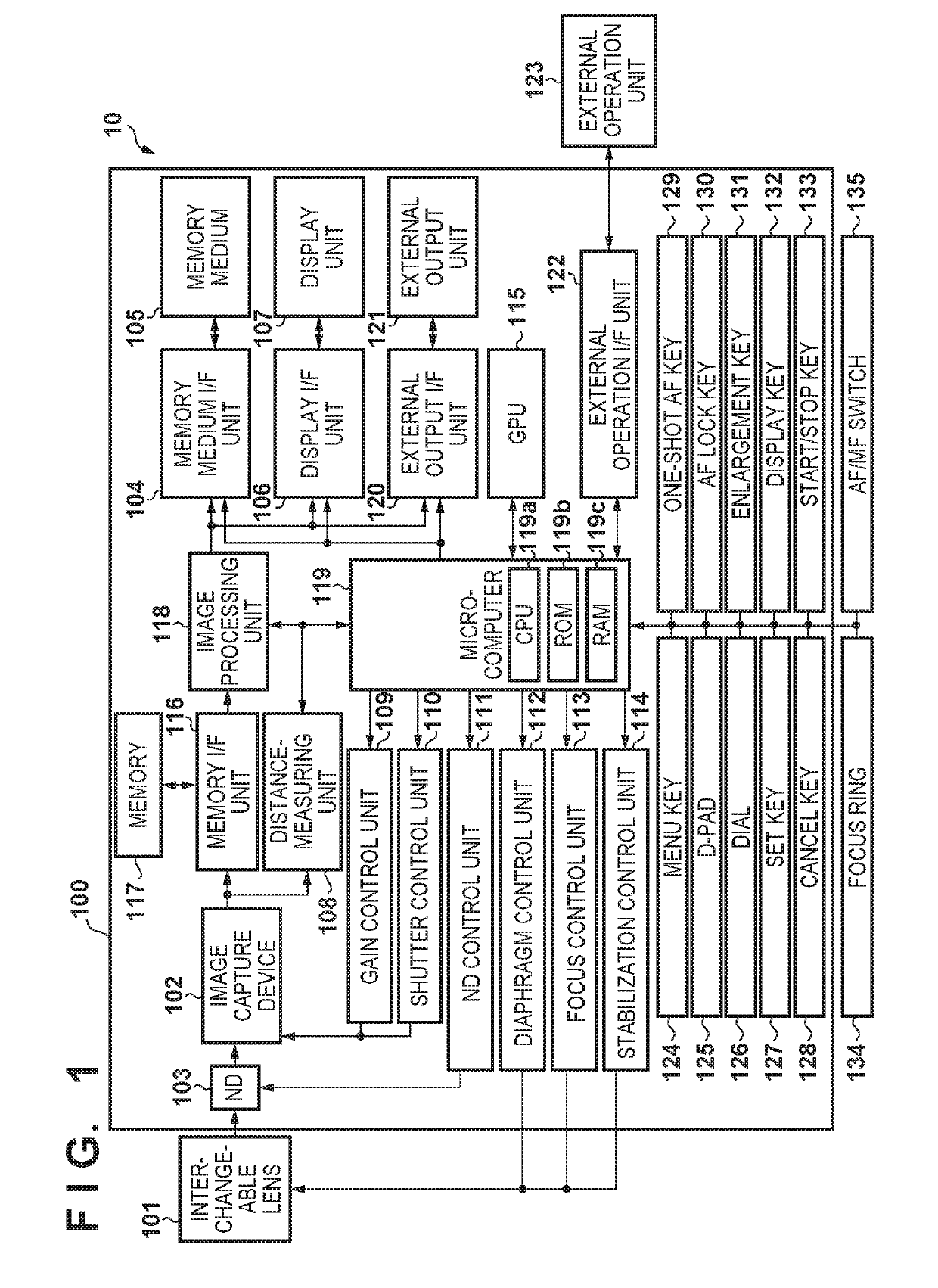
[0019]FIG. 1 shows an example of the hardware configuration of a digital camera 10 serving as an example of a display control apparatus of a first embodiment. In FIG. 1, a casing 100 is an external covering that contains many of the constituent elements of the digital camera 10. Various types of operation units (124 to 135), a display unit 107 and an external output unit 121 are exposed on the surface of the casing 100. An interchangeable lens 101 is a taking lens that consists of a plurality of lens groups, and includes a diaphragm in addition to being provided internally with a focus lens, a zoom lens, and a shift lens.

[0020]An image capture device 102 has a configuration in which a plurality of pixels each having a photoelectric conversion element are arrayed two-dimensionally. The image capture device 102 performs photoelectric conversion with the pixels on an object optical image formed by the interchangeable lens 101, and further performs analog-to-digita...

second embodiment

[0072]In the first embodiment, the focus guide frame is displayed in a central area of enlarged display, when the focus guide frame leaves the screen (leaves the enlarging area). However, the present invention is not limited thereto. In the second embodiment, the focus guide frame is displayed in a central area of enlarged display, in the case where the operation for moving the enlarging area exceeds a predetermined number of times. Note that the hardware configuration is similar to the first embodiment.

[0073]FIGS. 8A to 8D show examples of screens that are displayed on the display unit 107 when the “captured image enlarged display” function is operated in the second embodiment. Unlike the exemplary screen c2 in FIG. 4C, in the state of FIG. 8B, a focus guide frame 801 is displayed in the center of the enlarged display. Since the operation for moving the enlarging area exceeds a predetermined operation amount, when having moved from the enlarging position of the screen display of FI...


PUM


Abstract

A display control apparatus: displays an enlarged image of an enlarging area including a first focus measurement area and a focus guide corresponding to the first focus measurement area; moves the enlarging area in the captured image, in response to a moving instruction from a user that does not satisfy a predetermined condition, and displays an enlarged image of an enlarging area whose position was changed by the moving instruction and a focus guide that corresponds to the first focus measurement area; and newly sets, in response to a moving instruction from a user that satisfies the predetermined condition, a second focus measurement area in a predetermined area of an enlarging area whose position was changed by the moving instruction, and displays an enlarged image of the enlarging area and a focus guide that corresponds to the second focus measurement area.

Description

BACKGROUND OF THE INVENTIONField of the Invention[0001]The present invention relates to a display control apparatus and a control method for the same, and more particularly to a display technology for focus-related information.Description of the Related Art[0002]There is a problem with recent video cameras in that it is difficult to focus with the viewfinder (VF) or small attached monitor at the time of shooting in high resolution such as 4K shooting or 8K shooting. In order to solve that problem, there is a function of displaying a guide relating to focusing in a designated area, for example (Japanese Patent Laid-Open No. 2016-197180 (hereinafter, Document 1)). There is also a function of enlarging the captured image of a designated area to assist focusing, and there also exists a focusing function of coordinating the operations of the camera with that function (Japanese Patent Laid-Open No. 2008-211630 (hereinafter, Document 2)).[0003]According to Document 1, when enlargement of a...

Claims


Application Information

Patent Timeline
Patent Type & Authority Applications(United States)
IPC IPC(8): H04N5/232
CPCH04N5/232945H04N5/232935H04N23/672H04N23/675H04N23/632H04N23/635H04N23/10
Inventor ISE, TOSHIMICHI
Owner CANON KK
Why Eureka
Try Eureka