Medical Scope Accessory, Medical Scopes Comprising The Accessory, And Use Thereof

a technology of medical scopes and accessories, applied in the field of medical scope accessories and medical scopes comprising accessories, can solve the problems of affecting the ability of the endoscopist to visualise affecting the ability of the endoscopist to see the entire surface of the mucosa, and significant risks of potentially serious complications

Active Publication Date: 2019-06-20
KEYMED MEDICAL & INDAL EQUIP
View PDF0 Cites 1 Cited by
  • Summary
  • Abstract
  • Description
  • Claims
  • Application Information

AI Technical Summary

Benefits of technology

[0008]The invention provides a cover for a shaft of a medical scoping device, the cover comprising a tubular member arranged for application over a distal tip of the medical scoping device shaft with the tubular member, in use, extending along a portion of the length of the distal end of the shaft, the tubular member comprising a proximal circumferential edge, a distal circumferential edge, an inner surface at least a part of which grips the shaft, and an outer surface, the cover comprising a plurality of projecting elements spaced apart circumf

Problems solved by technology

Whilst colonoscopic and enteroscopic examinations are the most effective techniques to assess the state of health of the bowel, they are inconvenient, uncomfortable, expensive procedures that are associated with significant risks of potentially serious complications.
In all endoscopic examinations, folds present may hamper the endoscopist's ability to visualise t

Method used


Image

  • Medical Scope Accessory, Medical Scopes Comprising The Accessory, And Use Thereof
  • Medical Scope Accessory, Medical Scopes Comprising The Accessory, And Use Thereof
  • Medical Scope Accessory, Medical Scopes Comprising The Accessory, And Use Thereof

Examples


first embodiment

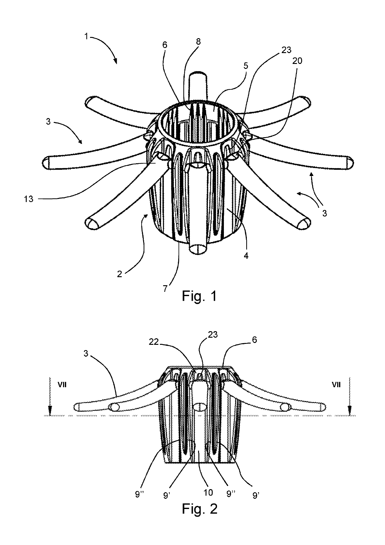
[0040]FIG. 1 is a perspective view of cover according to the invention for use in sigmoidoscopy.

[0041]FIG. 2 is a side view of the cover of FIG. 1;

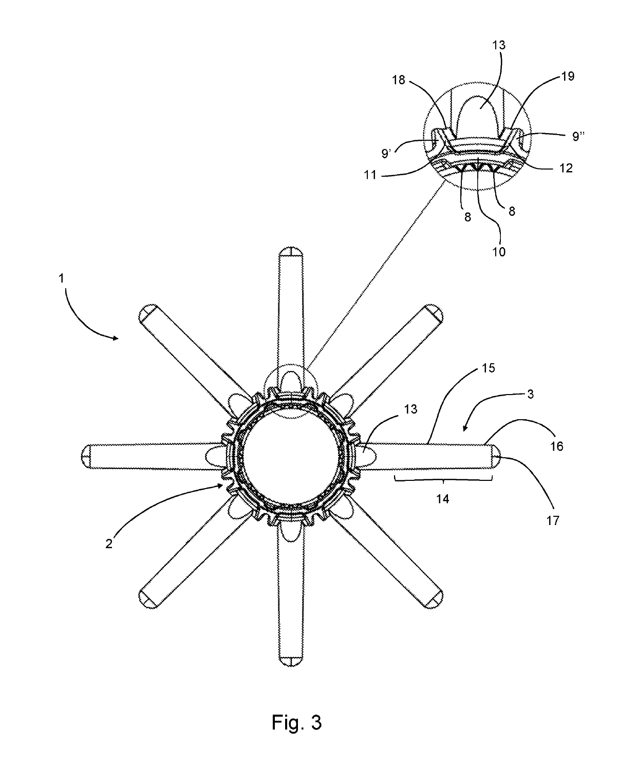
[0042]FIG. 3 is a bottom view of the cover of FIG. 1 and includes a detail view showing a portion of the base of a projecting element and the adjacent portion of the tube;

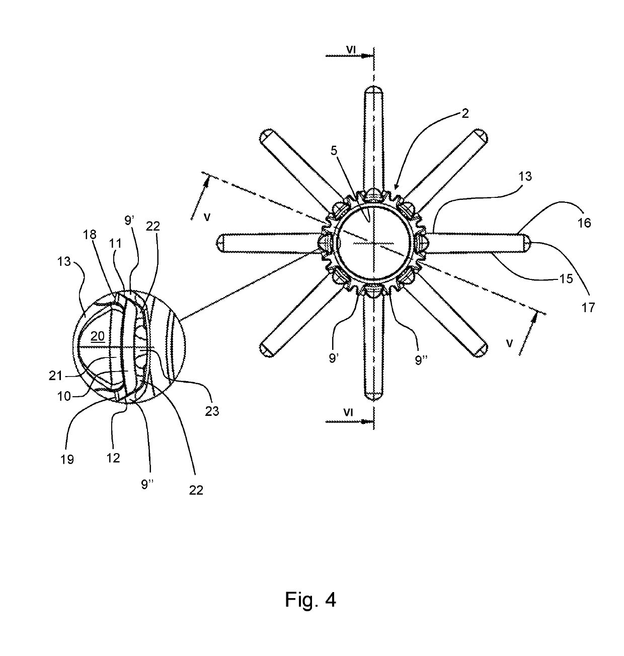
[0043]FIG. 4 is a view of the cover of FIG. 1 from above, showing a detail of a portion of the cover at the base portion of a projection element;

[0044]FIG. 5 is a vertical section through the cover of FIGS. 1 to 4 along the line V-V shown in FIG. 4;

[0045]FIG. 6 is a vertical section through the cover of FIGS. 1 to 4 along the line VI-VI shown in FIG. 4, further showing in section a detail of a portion of the cover showing the base portion of the projecting element and the adjacent portion of the tube in section;

[0046]FIG. 7 is a horizontal section along the line VII-VII of FIG. 2;

second embodiment

[0047]FIG. 8 is a perspective view of cover according to the invention for use in enteroscopy;

[0048]FIG. 9 is a bottom view of the cover of FIG. 8 and includes a detail view showing a portion of the base of a projecting element and the adjacent portion of the tube;

[0049]FIG. 10 is a view of the cover of FIG. 1 from above, showing a detail of a portion of the cover at the base portion of a projection element;

[0050]FIG. 11 is a section through a cover according to FIGS. 1 to 7 in the rest position;

[0051]FIG. 12 is a section through the cover of FIG. 11 showing the projecting elements in a forward position;

[0052]FIG. 13 is a schematic view of a cover according to the invention as used in a first stage of colonoscopic examination;

[0053]FIG. 14 is a schematic view of the cover of FIG. 13 during a main visualisation stage of a colonoscopic examination;

third embodiment

[0054]FIG. 15 is a perspective view of a projecting element for use in a cover according to the invention;

[0055]FIG. 16 is a partial side view of the cover of the third embodiment of the invention in which the projecting elements are in an extreme distal position; and

[0056]FIG. 17 is a section through the cover shown in FIG. 16 along the line A-A shown in FIG. 16

[0057]The invention is described hereafter with reference to first and second illustrative embodiments of the invention comprising a tip cover device for sigmoidoscopy (FIGS. 1 to 7) and a tip cover device for enteroscopy (FIGS. 8 to 10). The invention may be applied in cover devices suitable for other types of internal examination, for example endoscopy, colonoscopy, and any other technique in which a visualisation device is advanced into a bodily orifice for examination.

[0058]FIGS. 1 to 7 show, as a first illustrative embodiment of the invention, a scope cover of dimensions suitable for mounting on the end of a sigmoidosco...


PUM


Abstract

A cover (1) for a shaft of a medical scoping device comprises tubular member (2) arranged for application on the distal tip of the medical scoping device. The cover (1) comprises a plurality of projecting elements (3) spaced apart circumferentially around the tubular member (2), each projecting element having a base portion (13) and an arm portion (14). The projecting elements are pivotably mounted on the tubular member about a pivot axis. The base portion (13) comprises a detent (20), and the tubular member comprises a contact region, for example a protuberance (23), said contact region being located such that pivoting movement of the projecting element for moving the arm portion in a distal direction can effect impacting of the detent (20) on the contact region (23).

Description

FIELD OF THE INVENTION[0001]The present invention relates to a device for use with a medical scoping device shaft and to a medical scoping device including a said device.BACKGROUND OF THE INVENTION[0002]In endoscopic examinations / procedures, flexible instruments designed to view the gastrointestinal tract are inserted along a body cavity to an internal part such as the stomach, duodenum, small intestine or large intestine. The instruments are provided with imaging devices, for example fibre-optic or charge-couple device (CCD) cameras, which enable images to be transmitted around bends and images to be produced to a display screen. Accordingly, it is possible to view the inside surfaces of the oesophagus, stomach and duodenum using a gastroscope, the small intestine with an enteroscope, part of the colon using a flexible sigmoidoscope and the whole of the large intestine (the bowel) with a colonoscope.[0003]Enteroscopy is the endoscopic examination of the small intestine whereas colo...

Claims


Application Information

Patent Timeline
IPC IPC(8): A61B1/32A61B1/00A61B1/31
CPCA61B1/32A61B1/0014A61B1/00101A61B1/31A61B2090/3966A61B1/00A61B1/00087A61B1/00089A61B1/00135A61B1/00142A61B2017/00296A61B1/00148
Inventor AXON, PATRICK
Owner KEYMED MEDICAL & INDAL EQUIP
Why Eureka
Try Eureka