
Motor frame with bumps

a technology of motor frame and bump, which is applied in the direction of electrical equipment, dynamo-electric machines, supports/enclosements/casings, etc., can solve the problems of motors that are eventually burned down or damaged, and are harmful to so as to achieve the effect of harming the entire heat dissipation of motors

Inactive Publication Date: 2019-06-20
TECO ELECTRIC AND MACHINERY
View PDF3 Cites 1 Cited by
  • Summary
  • Abstract
  • Description
  • Claims
  • Application Information

AI Technical Summary

Benefits of technology

The present invention provides a motor frame with bumps that create a heat-dissipation flow circulation space, resulting in improved heat-dissipation efficiency. The bumps are positioned radially outwards to conduct heat transfer to heat-dissipation fins, which in turn transfer the thermal energy to the atmosphere through the frame body. The heat-dissipation fins are more efficient in dissipating the thermal energy, and the space occupied by the frame is reduced. The goal of lightweight can be achieved without sacrificing heat-dissipation performance.

Problems solved by technology

In view of the prior art, since the existence of the wiring passages may sacrifice the amount of the heat-dissipation fins.
It can be foreseen that, under such an operation situation, the motor would be eventually burned down or damaged at least.
In addition, hot spots would cause a non-uniform temperature distribution inside the motor frame, and thus would be harmful to the entire heat dissipation of the motor.

Method used


Image

  • Motor frame with bumps
  • Motor frame with bumps
  • Motor frame with bumps

Examples


Embodiment Construction

[0028]The invention disclosed herein is directed to a motor frame with bumps. In the following description, numerous details are set forth in order to provide a thorough understanding of the present invention. It will be appreciated by one skilled in the art that variations of these specific details are possible while still achieving the results of the present invention. In other instance, well-known components are not described in detail in order not to unnecessarily obscure the present invention.

[0029]Refer now to FIG. 4 and FIG. 5; where FIG. 4 is a schematic perspective view of a preferred embodiment of the motor frame with bumps in accordance with the present invention, and FIG. 5 is a schematic front view of FIG. 4. As shown, the motor frame with bumps (“motor frame” thereafter) 1 includes a frame body 11, a plurality of bumps 12 (only one labeled in the figure) and a plurality of heat-dissipation fins 13 (only one labeled in the figure). In this preferred embodiment, the moto...


PUM


Abstract

A motor frame with bumps includes a frame body, plural bumps and plural heat-dissipation fins. The frame body has an internal surface and an external surface. Each of the bumps protrudes radially inward from the inner surface, and plural internal flow passages are formed by every two neighboring bumps. Each of the heat-dissipation fins protrudes radially outward from the external surface, and plural external flow passages are formed by every two neighboring heat-dissipation fins. Each of the bumps is radially outwards respective to at least two of the heat-dissipation fins.

Description

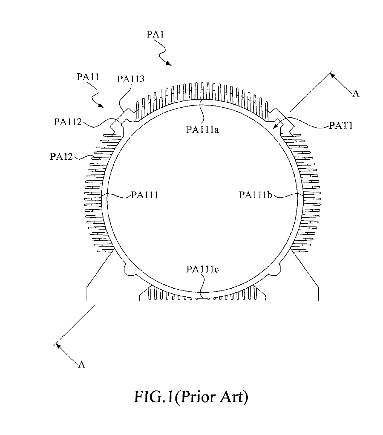
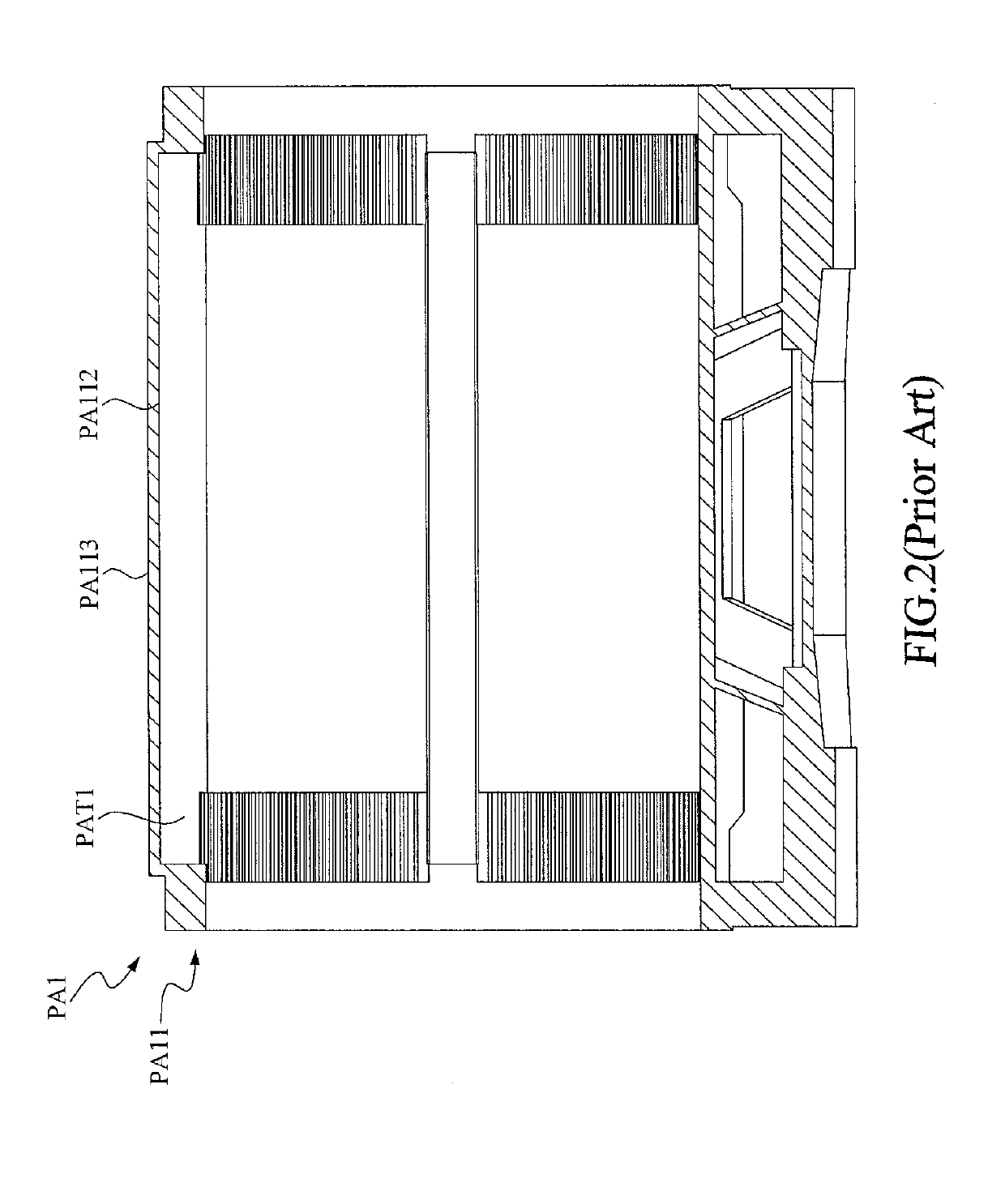
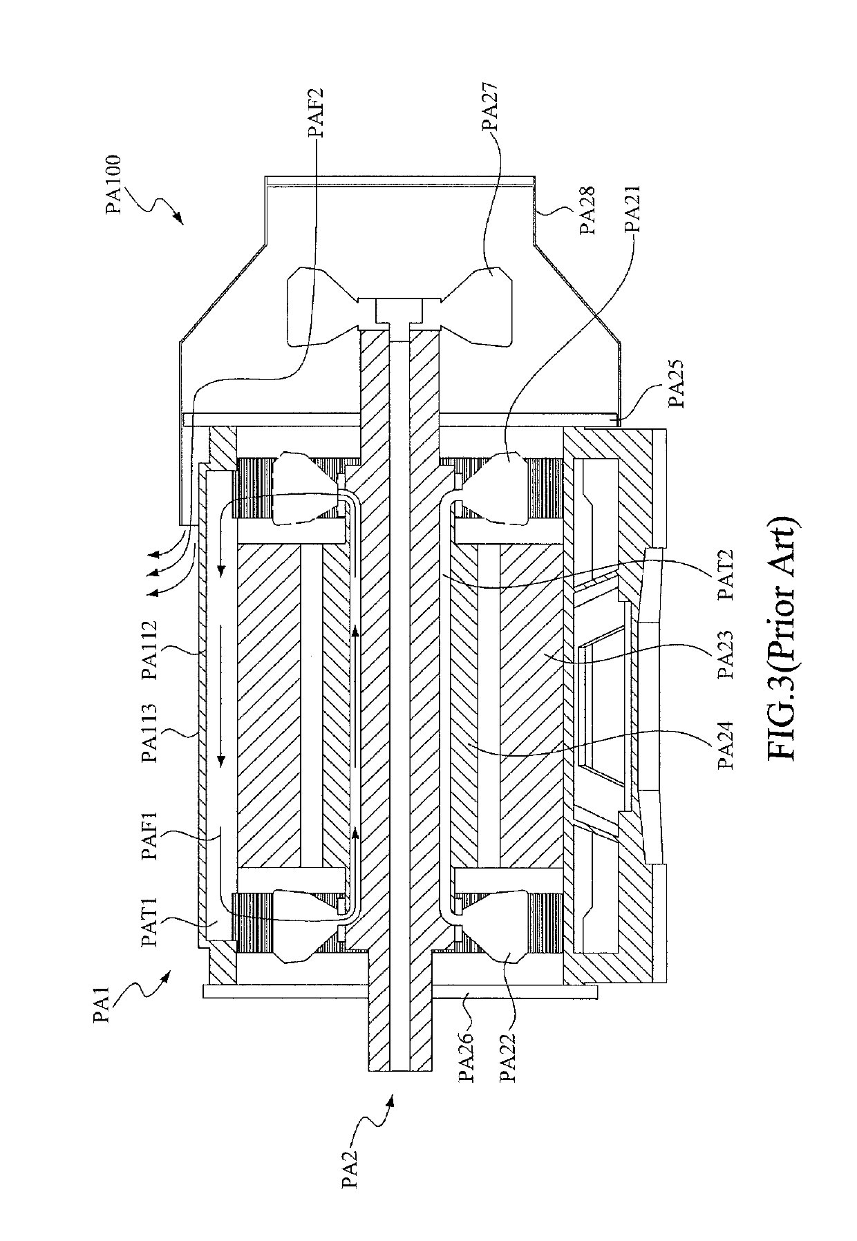
BACKGROUND OF THE INVENTION1. Field of the Invention[0001]The invention relates to a motor frame, and more particularly to the motor frame having bumps for heat conduction.2. Description of the Prior Art[0002]A motor is a device that can transform electric energy into mechanical kinetic energy by electromagnetic induction. While in transforming the electric energy into the corresponding kinetic energy, electric current would flow through stator coils, so that corresponding electromagnetic effect can be induced. However, while the electric current flows, excess thermal energy would be generated due to current loss (for example, copper loss or iron loss) from electric resistance of the stator coils. This thermal energy would somehow damage internal elements of the motor, and further affect the operation of motor.[0003]In details, refer to FIG. 1 through FIG. 2; where FIG. 1 is a schematic front view of a conventional motor frame, and FIG. 2 is a schematic cross-sectional view of FIG. ...

Claims


Application Information

Patent Timeline
Patent Type & Authority Applications(United States)
IPC IPC(8): H02K5/18H02K9/08
CPCH02K5/18H02K9/08
Inventor WANG, CHI-HSINTSAI, CHENG-HANFANG, ZIH-YANG
Owner TECO ELECTRIC AND MACHINERY
Learn More