Drag knob and fishing reel

Active Publication Date: 2019-06-27
SHIMANO INC
View PDF11 Cites 0 Cited by
  • Summary
  • Abstract
  • Description
  • Claims
  • Application Information

AI Technical Summary

Benefits of technology

The present disclosure improves the economic efficiency, design, and operability of a drag knob by using an operating member that can be easily replaced. The operating member is divided into a cover and an insert, allowing for various designs. The fixing member and sounding member are positioned to overlap with the knob, making it easy to grip and use. This results in an improved user experience and efficient use of the drag knob.

Problems solved by technology

In a conventional drag knob in which the operating member is constituted from a single member, since only the knob is operated, only the knob undergoes frictional wear, particularly when the knob is operated while wearing fishing gloves.
In addition, dropping of the drag knob can lead to damage to the knob.
Such a case could require replacement of the entire drag knob, which is problematic in terms of economic efficiency.
In addition, since the drag knob is located on the front of the fishing reel, design-related problems arise.

Method used


Image

  • Drag knob and fishing reel
  • Drag knob and fishing reel
  • Drag knob and fishing reel

Examples


Embodiment Construction

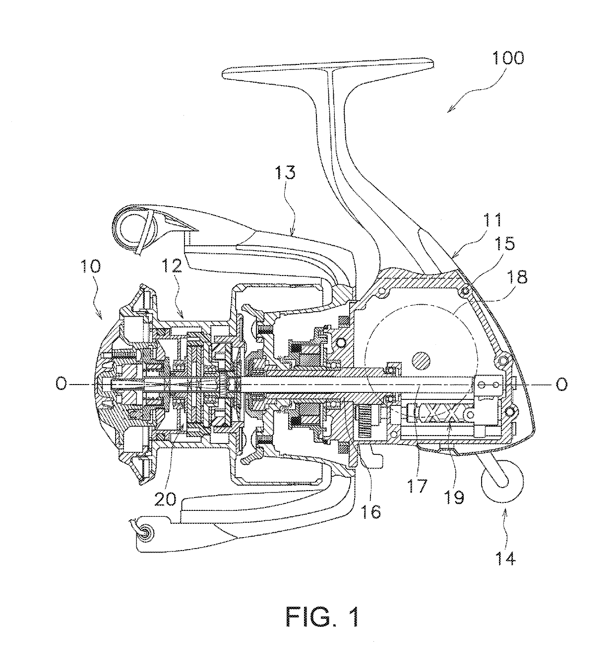
[0022]A preferred embodiment of a spinning reel will be described with reference to the drawings. Note that in the description that follows, unless otherwise specified, “axial direction” denotes the direction in which rotation center O of a rotor 13 extends, “radial direction” denotes the radial direction of a circle around the rotation center O, and “circumferential direction” denotes the circumferential direction of a circle centered on the rotation axis. In addition, “front” denotes the direction in which a fishing line is cast (the left direction in FIG. 1), while “rear” refers to the opposite direction (the right direction in FIG. 1).

[Spinning Reel]

[0023]As shown in FIG. 1, a spinning reel 100 reels out fishing line to the front (to the left in FIG. 1). The spinning reel 100 includes a reel body 11, a spool 12, a rotor 13, a handle 14, and a drag knob 10.

[Reel Body]

[0024]The reel body 11 has a housing 15, a pinion gear 16, and a spool shaft 17. The reel body 11 also has a drive...


PUM


Abstract

A drag knob includes an operating member and a sounding member. The operating tuber has a cover, an insert, and a bolt serving as a fixing member for fixing the cover to the insert. The operating member is rotatably attached to a reel body. The sounding member produces a percussive sound by rotation of the operating member. The operating member has a knob that extends in a radial direction. The bolt and the sounding member are disposed so as to overlap with the knob when viewed in an axial direction.

Description

CROSS-REFERENCE TO RELATED APPLICATIONS[0001]This application claims priority to Japanese Patent Application No. 2017-250530, filed Dec. 27, 2017. That application is incorporated by reference in its entirety.BACKGROUNDTechnical Field[0002]The present disclosure relates to a drag knob, and in particular to a drag knob for adjusting the drag force of a drag mechanism by being screwed into the front end of a spool shaft on which is mounted a spool of a spinning reel.Background Information[0003]A fishing reel is generally provided with a drag mechanism for braking the rotation of a spool. The drag mechanism can regulate the drag force by rotation of the drag knob. For example, a drag knob having a sounding mechanism is disclosed in Japanese Laid Open Patent Application No. 2006-136216 (Patent Document 1). When the drag knob described in this publication is rotated, a striking pin provided in the sounding mechanism repeatedly makes contact with sounding recesses, whereby sound is produc...

Claims


Application Information

Patent Timeline
IPC IPC(8): A01K89/027
CPCA01K89/027A01K89/006A01K89/0111
Inventor SAITO, KEIDEGUCHI, TOMOYA
Owner SHIMANO INC
Why Eureka
Try Eureka