Eureka AIR delivers breakthrough ideas for toughest innovation challenges, trusted by R&D personnel around the world.

Electric door lock device

Inactive Publication Date: 2019-07-04
GIANNI INDS
View PDF18 Cites 4 Cited by
  • Summary
  • Abstract
  • Description
  • Claims
  • Application Information

AI Technical Summary

Benefits of technology

The present invention provides an electric door lock device with safety features. The device includes a housing with a chamber, a tongue, a latch, a sliding member, a follower, a lever arm, a rotary member, a link, and an actuator. The sliding member is engaged with a passage in the sliding member and a follower for selectively engaging and moving the latch. The lever arm is attached to the housing and engaged with the follower for moving it up and down. The rotary member is attached to the housing and includes a stud for rotating the lever arm. The link is engaged with the rotary member for rotating it. The actuator may include a mandrel connected to the link for moving it up and down. The beam is connected to the mandrel and the pivot post for allowing it to be pivoted relative to the housing. This invention ensures safe and safe operation of the electric door lock device.

Problems solved by technology

However, after the door panel is locked with or by the typical electromagnetic deadbolt lock devices, the deadbolt or tongue may be contacted and forced onto the parts or elements of the electromagnetic deadbolt lock devices with a preload which may have the electromagnetic deadbolt lock devices be jammed such that the electromagnetic deadbolt lock devices may not be easily actuated or operated by the user.

Method used


Image

  • Electric door lock device
  • Electric door lock device
  • Electric door lock device

Examples


Embodiment Construction

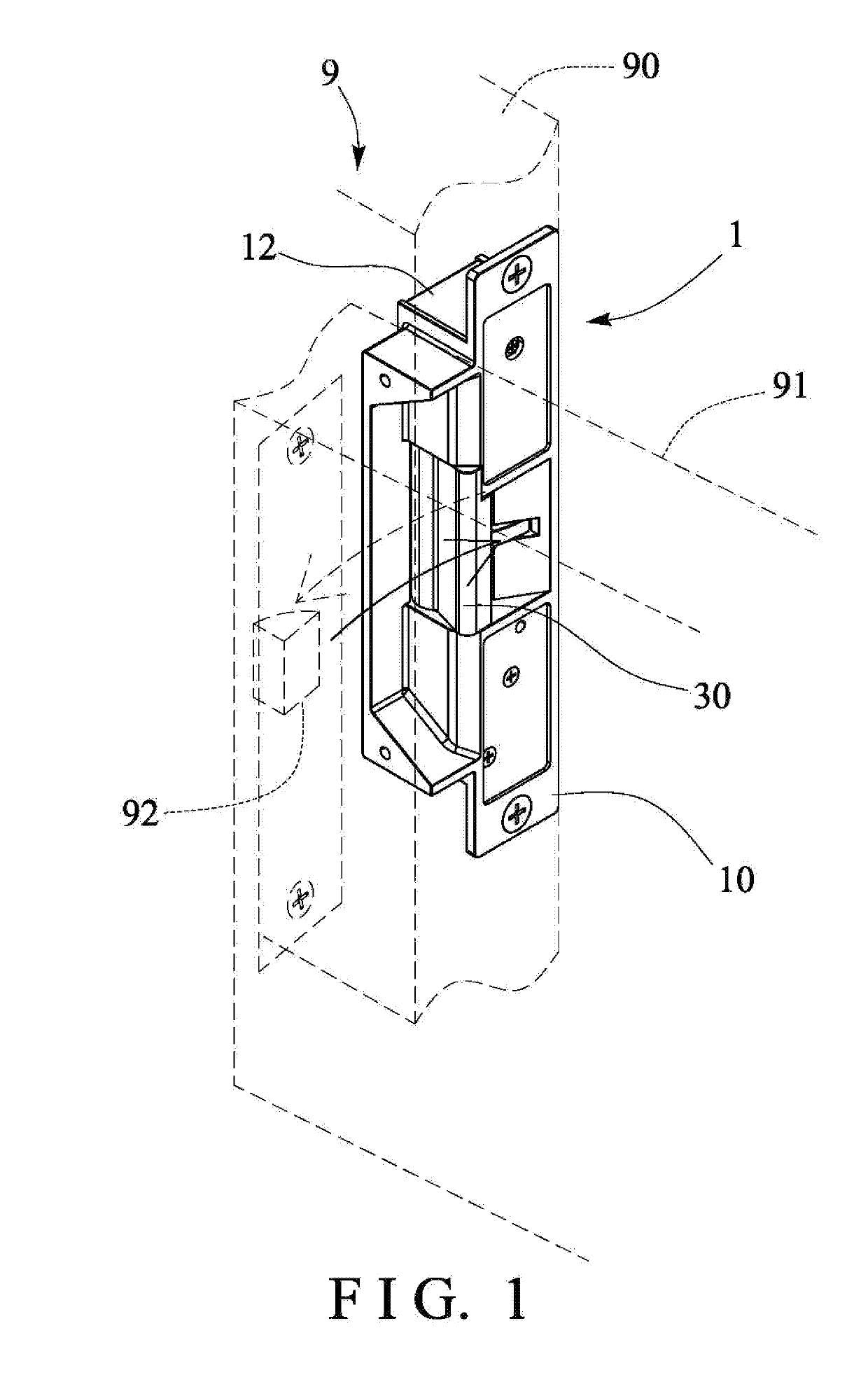
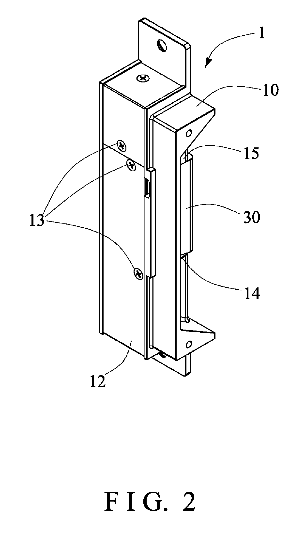
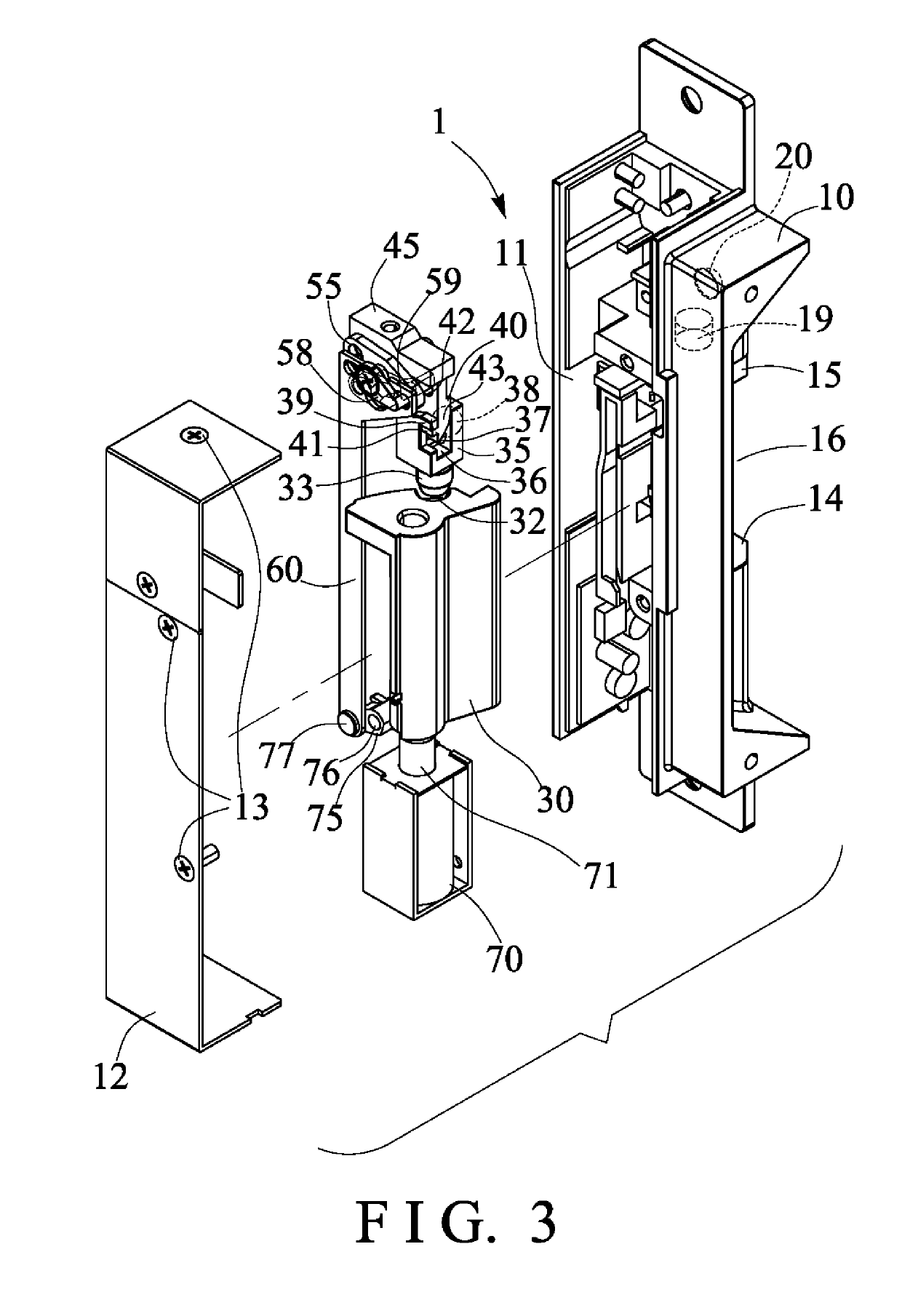
[0022]Referring to the drawings, and initially to FIG. 1, an electric door lock device 1 in accordance with the present invention is developed and provided for attaching or mounting or securing to a door member or door panel 90 of a door device 9, for locking and unlocking the door device 9, and the door panel or door member 90 of the door device 9 is worked in cooperate with a door element 91 of the door device 9, such as a door panel, a door frame 91 or the like. The door frame or door element 91 of the door device 9 includes a latch bolt 92 formed or provided or engaged therein. As shown in FIGS. 1-5, the electric door lock device 1 in accordance with the present invention comprises a housing 10 disposed or engaged into the door member 90 (FIG. 1), and including a chamber 11 formed therein (FIGS. 3, 4) for receiving various parts or members or elements or the like therein.

[0023]The electric door lock device 1 or the housing 10 includes a cover 12 secured onto the housing 10, such...


PUM


Abstract

A door lock device includes a tongue pivotally engaged in a housing, a latch slidably received in the housing for latching the tongue to the housing, a sliding member located above the latch for forcing the latch to engage with the tongue, a follower slidably engaged in the sliding member and having a projection for moving the sliding member away from the tongue, a lever arm is pivotally attached to the housing and includes an end portion engaged with the follower for moving the follower up and down relative to the sliding member and the housing, a rotary member is attached to the housing and includes a stud engaged with the lever arm for rotating the lever arm relative to the housing, and a link is slidably engaged in the housing and connected to the rotary member.

Description

BACKGROUND OF THE INVENTION1. Field of the Invention[0001]The present invention relates to a door lock device, and more particularly to an electric door lock device including a safety structure or mechanism for allowing the electric door lock device to be suitably and safely operated or actuated.2. Description of the Prior Art[0002]Various kinds of typical electromagnetic lock devices, such as electric dropbolts, cathode locks or the like have been developed and provided for conducting or operating or locking and unlocking various door devices, and normally comprise a core or deadbolt actuatable or movable or operatable with a coil or an electromagnetic mechanism to actuate the deadbolt or tongue and to lock or unlock a door or window or the like.[0003]For example, U.S. Pat. No. 4,677,834 to Hicks, U.S. Pat. No. 5,531,086 to Bryant, U.S. Pat. No. 5,566,991 to Young, U.S. Pat. No. 5,934,720 to Karalius, U.S. Pat. No. 6,079,755 to Chang, U.S. Pat. No. 6,302,455 to Huang, U.S. Pat. No....

Claims


Application Information

Patent Timeline
IPC IPC(8): E05B47/06
CPCE05B47/0603E05B47/0696E05B47/0003E05B47/0047
Inventor CHANG, CHIH CHUNG
Owner GIANNI INDS
Why Eureka
Eureka Blog
Learn More