Pneumatic Tire

a pneumatic tire and rib technology, applied in the field of pneumatic tires, can solve the problems of reducing the rigidity of the rib, affecting the performance of steering stability on dry road surfaces, and affecting the smoothness of the tyre, so as to improve the drainage effect, and improve the wet performance

Active Publication Date: 2019-07-25
THE YOKOHAMA RUBBER CO LTD
View PDF0 Cites 1 Cited by
  • Summary
  • Abstract
  • Description
  • Claims
  • Application Information

AI Technical Summary

Benefits of technology

[0005]The present technology provides a pneumatic tire in which, by devising a sipe chamfer shape, in addition to improving snow performance, improvement in steering stability performance on dry road surfaces and improvement in steering stability performance on wet road surfaces are both enabled.
[0007]According to the present technology, in a pneumatic tire having a sipe extending in the tire width direction on a rib defined by a main groove, while a chamfered portion shorter than the sipe length of the sipe is provided in each of the leading edge side and trailing edge side of the sipe, there is a non-chamfered region having no other chamfered portion in the part facing each chamfered portion in the sipe, thereby improving the drainage effect based on the chamfered portion, and at the same time, the non-chamfered region is capable of effectively removing the water film by the edge effect. This thereby enables steering stability on wet road surfaces to be significantly improved. Moreover, since the chamfered portion and the non-chamfered region are mixed in each of the leading side edge and the trailing side edge, the beneficial effect of improving the wet performance as described above may be maximized at the time of braking and at the time of accelerating. Further, compared to the sipe chamfered in a conventional manner, since the area to be chamfered can be minimized, improvement in steering stability performance on dry road surfaces is enabled. As a result, achieving both improvement in the steering stability performance on dry road surfaces and improvement in the steering stability performance on wet road surfaces is enabled. Furthermore, since at least one of the chamfered portions has an outer edge profile line not parallel to the ridge line of the sipe in a plan view of the tread portion, the edge effect is obtained, enabling improvement in the steering stability performance on wet road surfaces and improvement in snow performance to be achieved at the same time.
[0009]In the present technology, it is preferable that, when a chamfered portion including the outer edge profile line not parallel to the ridge line of the sipe is divided into an inner region and an outer region corresponding to half a chamfer length of the chamfered portion in the tire width direction, a projected area Oa of the outer region positioned on the rib outer side is smaller than a projected area Ia of the inner region positioned on the rib inner side. This enables the steering stability performance on dry road surfaces and the steering stability performance on wet road surfaces to be improved effectively.
[0010]In the present technology, it is preferable that a ratio Ia / Oa of the projected area Ia of the inner region to the projected area Oa of the outer region is from 1.1 to 3.0. More preferably, a ratio Ia / Oa is from 1.5 to 2.5. This thereby enables the steering stability performance on dry road surfaces and steering stability performance on the wet road surfaces to be improved in a well-balanced manner. Note that, the projected area Ia of the inner region and the projected area Oa of the outer region of the chamfered portion are the areas of the respective regions measured when the tread portion is projected in the thickness direction.
[0011]In the present technology, it is preferable that the pneumatic tire has a designated mounting direction with respect to a vehicle, and the chamfered portion including the outer edge profile line not parallel to the ridge line of the sipe is positioned on a vehicle outer side. This thereby enables the steering stability performance on dry road surfaces to be improved effectively.

Problems solved by technology

However, when a large number of sipes are arranged in the tread portion for improving the steering stability performance on wet road surfaces, the rigidity of the rib is reduced, so that there is a disadvantage that steering stability performance on dry road surfaces is deteriorated.
When forming a sipe and chamfering it, the edge effect may be lost depending on the shape of chamfer, and improvement in the steering stability performance on dry road surface or the steering stability performance on wet road surface may be insufficient depending on the chamfering size.
However, when the groove volume of the tread portion is increased, since the block rigidity is lowered, the steering stability on wet road surfaces tends to deteriorate.
It is therefore difficult to achieve the steering stability on wet road surfaces and the snow performance in a compatible manner.

Method used


Image

  • Pneumatic Tire
  • Pneumatic Tire
  • Pneumatic Tire

Examples


examples

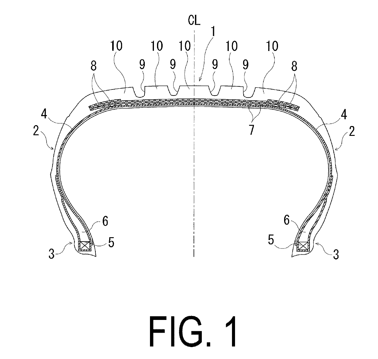
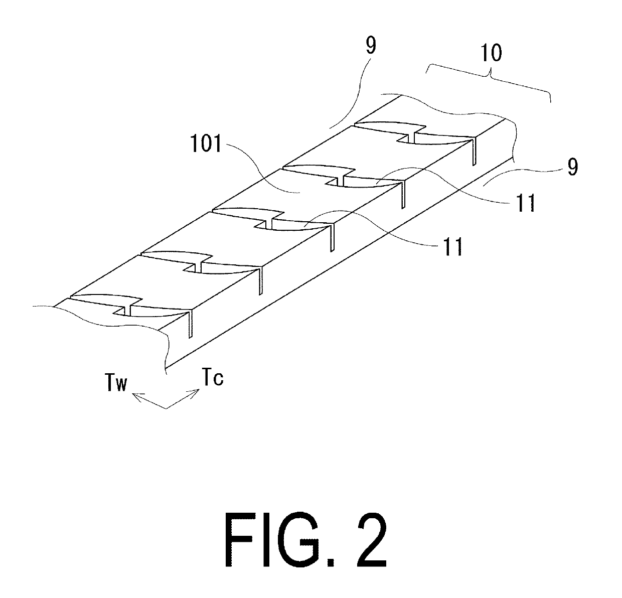
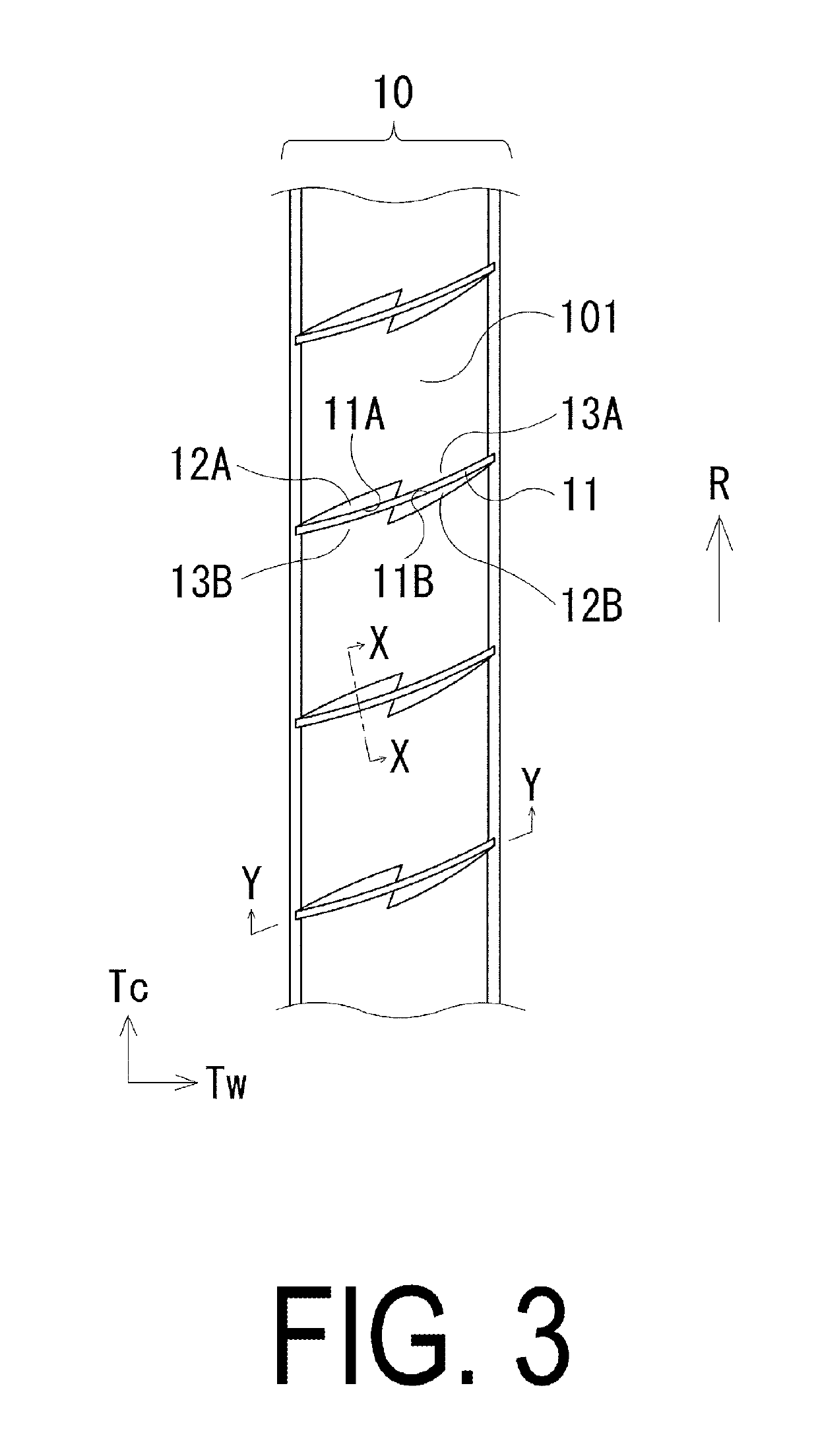
[0047]Pneumatic tires, including a plurality of main grooves extending in the tire circumferential direction in a tread portion, and sipes, extending in the tire width direction on a rib defined by the main grooves and having a tire size of 245 / 40 R19, were manufactured according to the following settings as shown in Tables 1 and 2 for the Conventional Examples 1, 2 and Examples 1 to 15: chamfer arrangement (both sides or one side); relationship between sipe length L and chamfer lengths LA, LB; whether the part facing a chamfered portion is chamfered; whether there is an outer edge profile line not parallel to the ridge line of the sipe at the chamfered portion; sipe maximum depth x (mm); chamfered portion maximum depth y (mm); ratio of projected area Ia of an inner region to projected area Oa of an outer region (Ia / Oa); position of chamfered portion (vehicle inner side or vehicle outer side); sipe inclination angle with respect to the tire circumferential direction; entire shape of...


PUM


Abstract

A pneumatic tire includes a plurality of main grooves extending in a tire circumferential direction in a tread portion; and a sipe extending in a tire width direction in a rib defined by the plurality of main grooves, the sipe including a leading side edge and a trailing side edge, a chamfered portion shorter than a sipe length of the sipe being formed in each of the leading side edge and the trailing side edge, a non-chamfered region including no other chamfered portion being present in a part facing each chamfered portion of the sipe, and, in a plan view of the tread portion, at least one of the chamfered portions including an outer edge profile line not parallel to a ridge line of the sipe.

Description

TECHNICAL FIELD[0001]The present technology relates to a pneumatic tire, and more particularly to a pneumatic tire in which, in addition to improved snow performance, improved steering stability performance on dry road surfaces and improved steering stability performance on wet road surfaces are can be achieved in a compatible manner, by devising a chamfered shape of a sipe.BACKGROUND ART[0002]Conventionally, in a tread pattern of a pneumatic tire, a plurality of sipes are formed on ribs defined by a plurality of main grooves. Such a sipe is provided such that drainage properties are ensured and steering stability performance on wet road surfaces is achieved. However, when a large number of sipes are arranged in the tread portion for improving the steering stability performance on wet road surfaces, the rigidity of the rib is reduced, so that there is a disadvantage that steering stability performance on dry road surfaces is deteriorated.[0003]Various proposals have been made on pne...

Claims


Application Information

Patent Timeline
Patent Type & Authority Applications(United States)
IPC IPC(8): B60C11/12
CPCB60C11/1236B60C11/1281B60C11/1204B60C11/1259B60C2011/1213B60C11/03B60C11/12B60C11/13B60C11/1392B60C2011/1209
Inventor SHIRAISHI, TAKAYUKIKOUDA, HIRAKUSHINZAWA, TATSUROUEMURA, TAKANORI
Owner THE YOKOHAMA RUBBER CO LTD
Why Eureka
Try Eureka