Operation apparatus
- Summary
- Abstract
- Description
- Claims
- Application Information
AI Technical Summary
Benefits of technology
Problems solved by technology
Method used
Image

Examples
first embodiment
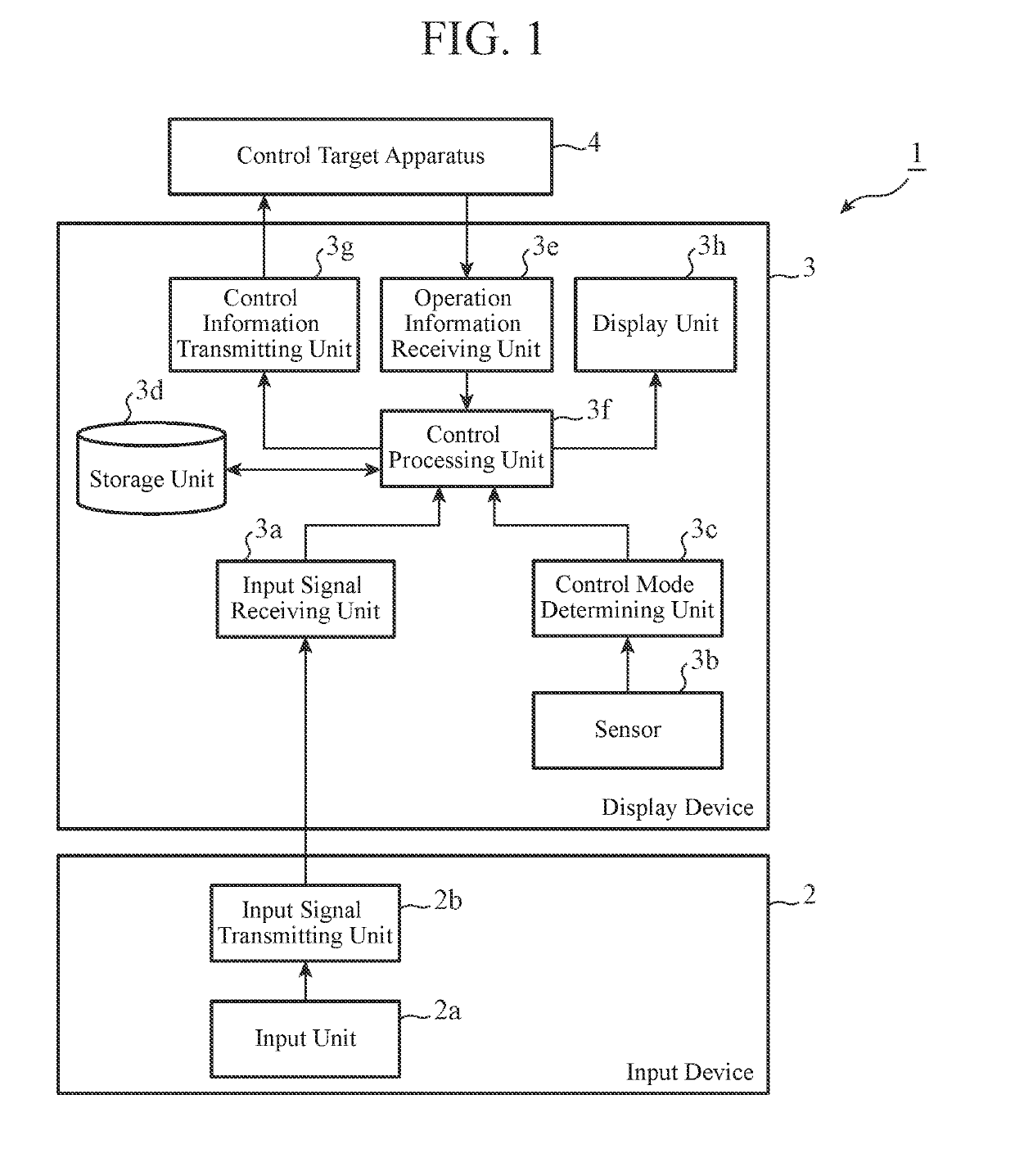
[0020]FIG. 1 is a block diagram showing a configuration of an operation apparatus 1 according to a first embodiment of the present invention.
[0021]The operation apparatus 1 is embodied by a remote controller that remotely controls an air conditioner and the like, and includes an input device 2 and a display device 3. The input device 2 can be combined with a part of the display device 3, and accepts a user operation and transmits an input signal to the display device 3. The input device 2 includes, as its configuration, an input unit 2a and an input signal transmitting unit 2b.
[0022]The input unit 2a accepts the user operation. For example, the input unit 2a has a hardware button and a switch disposed inside the input device 2, and outputs, to the input signal transmitting unit 2b, an input signal generated when the switch is pushed down by the hardware button.
[0023]The input signal transmitting unit 2b transmits the input signal from the input unit 2a to the display device 3. As a...
second embodiment
[0065]FIG. 5 is a block diagram showing a configuration of an operation apparatus 1A according to a second embodiment of the present invention.
[0066]Note that, in FIG. 5, the same components as those in FIG. 1 are denoted by the same reference numerals, and description thereof is omitted.
[0067]The operation apparatus 1A includes an input device 2 and a display device 3A.
[0068]The display device 3A includes an input signal receiving unit 3a, a sensor 3b-1, a control mode determining unit 3c, a storage unit 3d-1, an operation information receiving unit 3e, a control processing unit 3f-1, a control information transmitting unit 3g, and a display unit 3h.
[0069]The sensor 3b-1 embodies a detection unit in the present invention, and detects a positional relationship between the input device 2 and the display device 3A in a state in which the input device 2 and the display device 3A are combined. For example, when the display device 3A has a quadrangular outer shape in a planar view, expo...
third embodiment
[0092]FIG. 7 is a block diagram showing a configuration of an operation apparatus 1B according to a third embodiment of the present invention. Note that, in FIG. 7, the same components as those in FIG. 1 and FIG. 5 are denoted by the same reference numerals, and description thereof is omitted.
[0093]The operation apparatus 1B includes an input device 2 and a display device 3B. The display device 3B includes an input signal receiving unit 3a, a sensor 3b-1, a control mode determining unit 3c, a storage unit 3d-2, an operation information receiving unit 3e, a control processing unit 3f-2, a control information transmitting unit 3g, and a display unit 3h.
[0094]In addition to the first reference data described in the second embodiment, the storage unit 3d-2 stores a fourth reference data indicating positional relationships between the input device 2 and the display device 3B and a correspondence relationship between an apparatus corresponding to each of the positional relationships and ...
PUM
 Abstract
Description
Claims
Application Information
 - R&D Engineer
- R&D Manager
- IP Professional
- Industry Leading Data Capabilities
- Powerful AI technology
- Patent DNA Extraction
Browse by: Latest US Patents, China's latest patents, Technical Efficacy Thesaurus, Application Domain, Technology Topic.
© 2024 PatSnap. All rights reserved.Legal|Privacy policy|Modern Slavery Act Transparency Statement|Sitemap