Heat exchanger and components and methods therefor

a technology of heat exchangers and components, applied in the field of heat exchangers, can solve the problems of prone failure of braze joints, prone to external clogging of all monoblock cores, and prone to bar and plate monoblock cores

Inactive Publication Date: 2019-08-15
AIR RADIATORS PTY LTD
View PDF0 Cites 0 Cited by
  • Summary
  • Abstract
  • Description
  • Claims
  • Application Information

AI Technical Summary

Benefits of technology

[0023]Unlike monoblock cores which obtain their structural strength from being in a block, discrete tubular components need to be stronger individually to prevent damage during use and installation.
[0032]The fin portions may have a dimpled surface to improve heat transfer characteristics. Alternatively, the fin portions may include a series of louvred slots. In such louvred slots, the louvres are created from the planar material creating the fin portion. Creation of each louvre creates a consequent slot and the louvre lies out of the plane of the surrounding material. The louvres increase the air side pressure drop, enhance performance but lead to increased fouling of the core with debris. Alternatively, the fin portions may be plain with no dimples or louvres.
[0050]Preferably, the tubular components are able to be assembled separately with at least one of the header plates. The tubular components may be removable individually from at least one of the header plates. This allows for maintenance of individual components.

Problems solved by technology

There are many brazed joints between the inner fins and the adjacent plates and thus bar and plate monoblock cores are typically prone to failure through failure of these braze joints.
However, these braze joints are prone to failure through corrosion and erosion (such as by grit blasting in the field).
Additionally, all monoblock cores are prone to external clogging, especially at the front of the core, at the upstream side of the airflow direction through the core.
Servicing of monoblock cores requires the removal of the whole core in order to clean or replace which induces significant vehicle down times.
The individual tubular components are typically constructed of copper which is heavy and has a high initial cost and so is prohibitive in some applications.
Given the safety concerns in dealing with lead, lead solder is expensive to use.
Lead solder also has a relatively low strength, is prone to corrosion, relatively poor conductivity and has a limited temperature range of applications e.g. less than 200 degrees C. Furthermore, the Mesabi tubular components are formed from tubes which have been flattened from round tubing, thus the end of the tube portions are still round.
The production of flattened tubes from round tubes necessitates an additional working step to produce the tubes of required configuration and additionally presents the risk that the tubes will not be correctly installed in the radiator core.

Method used


Image

  • Heat exchanger and components and methods therefor
  • Heat exchanger and components and methods therefor
  • Heat exchanger and components and methods therefor

Examples


Embodiment Construction

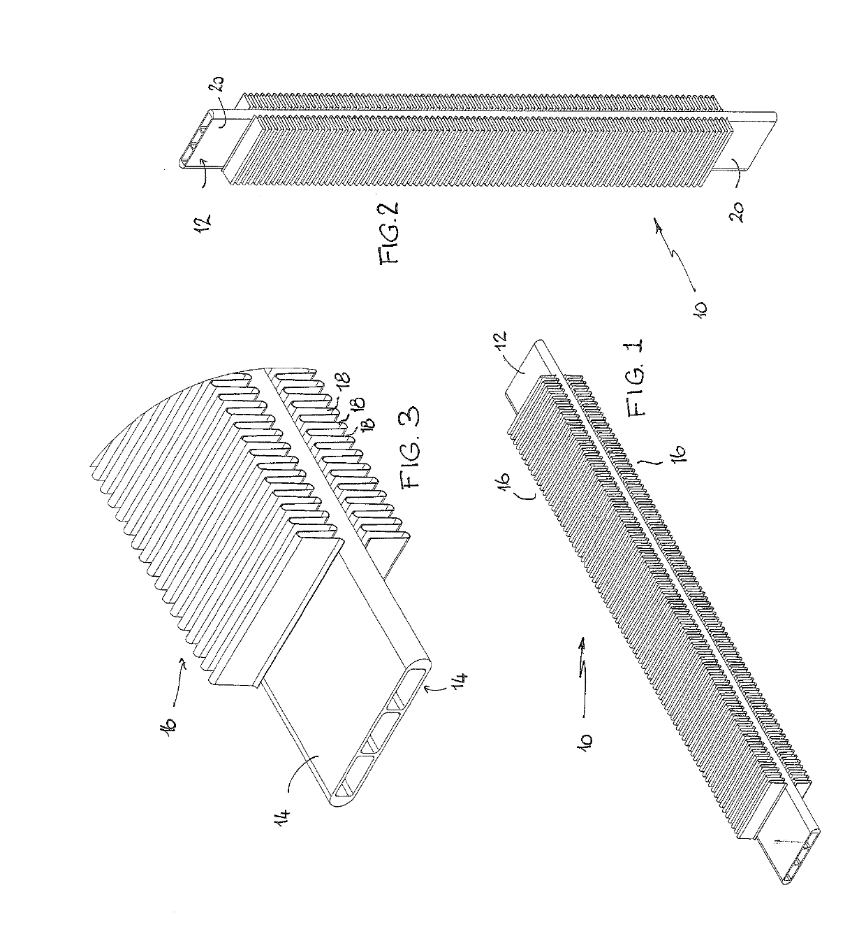
[0110]FIGS. 1 and 2 illustrate the form of the tubular component 10 according to a preferred embodiment of the present invention. The tubular component 10 includes a tube portion 12. The tube portion 12 is oblong in transverse section as shown in FIG. 3 with 2 flat longitudinal sides 14. Fin portions 16 are bonded to respective flat sides 14. As shown most clearly in FIG. 3, the fin portions 16 are in the form of metal strip which has been folded, bent, corrugated or otherwise shaped into repeated folds 18 of troughs and peak. The folds 18 are sinuous in shape and are of equal height and equal spacing between the folds. The fin portions 16 extend for a substantial portion of the length of the tube portion 12. However, the fin portions 16 fall short of the ends of the tube portion 12 and define end portions 20 which are free of the fin portions on both sides 14.

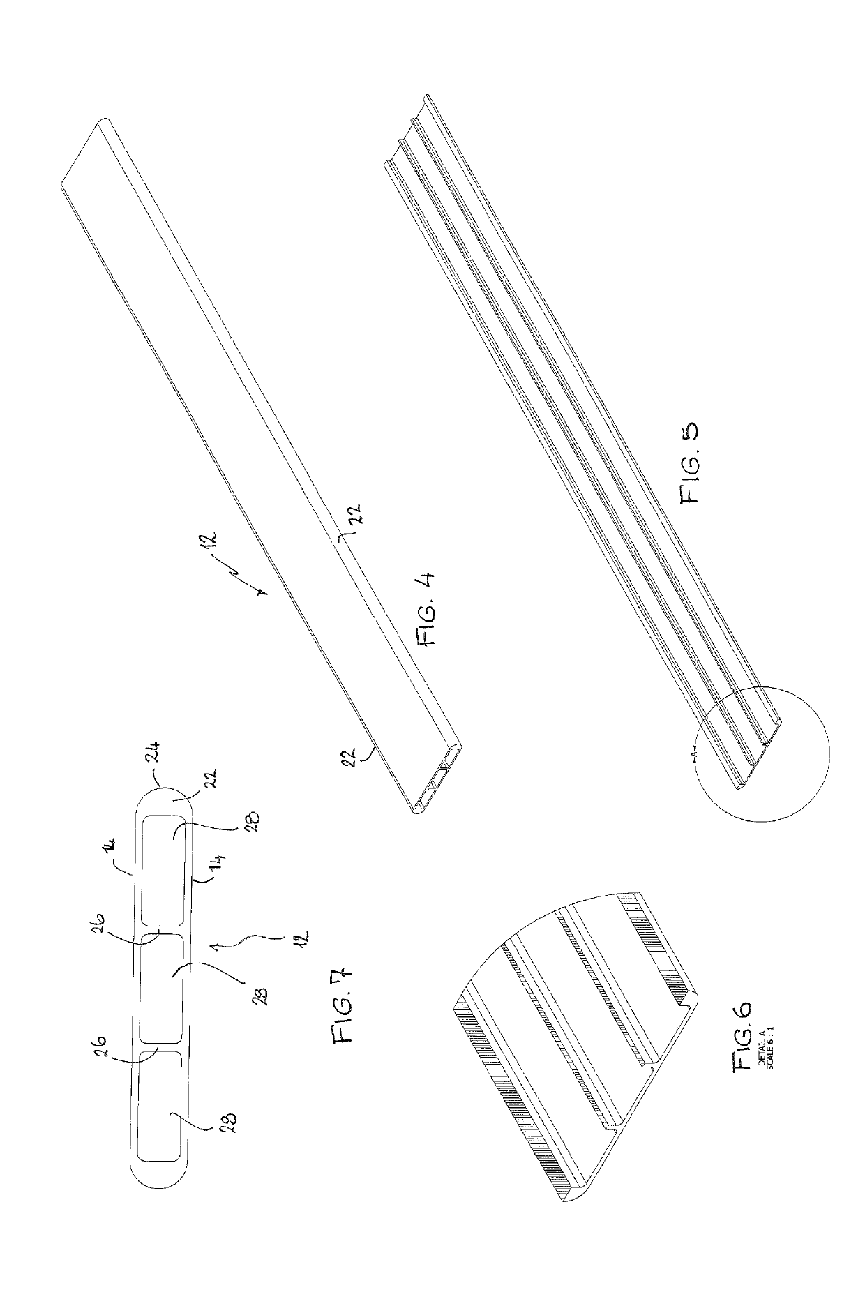
[0111]FIGS. 4-7 show the form of the tube portion 12 in greater detail. The tube portion 12 is extruded from a heat treatabl...


PUM

PropertyMeasurementUnit
melting pointaaaaaaaaaa
temperaturesaaaaaaaaaa

Abstract

A method of constructing discrete tubular components (10) for a heat exchanger (50) includes providing a tube portion (12) having substantially flat sides (14). Additionally, a metal strip is provided which includes a substrate material (32) and a second material (34) different than the substrate material forming a layer in the strip. The second material (34) is provided on only one side of the metal strip. The strip is configured in repeated folds of peaks and troughs to form fin portions (16). The tube and fin portions are assembled to form an array (37) of multiple bundles of one of the tube portions with the fin portions (16) arranged on the substantially flat sides (14) of the tube portion (12) and the second material (34) of the strip facing the tube portion (12), and one or more spacers (38) disposed between adjacent bundles. The array (37) is heated to bond the second material (34) to the tube portion (12) in the region of the troughs of the fin portions (16). The array (37) is separated into the discrete tubular components with, in each case, fin portions (16) bonded to the substantially flat sides (14) of each tube portion (12) with the peaks of the fin portions being exposed.

Description

FIELD OF THE INVENTION[0001]The present invention relates to heat exchangers. In particular, although not exclusively, the invention relates to a heat exchanger having separable tubular heat exchanger components extending between the tanks. The invention also relates to a discrete tubular component for a heat exchanger and a method of constructing a discrete tubular component.[0002]In particular, although not exclusively, the specification is also directed to aluminium tubular components for heat exchangers, particularly for heavy duty on-road and off-road applications. The inventions described herein may have application to air-to-air heat exchangers (charge air coolers) or liquid-to-air heat exchangers (water jacket coolers).BACKGROUND OF THE INVENTION[0003]Heat exchangers, particularly those used in vehicles and industrial machinery, come in a large variety tubing configurations, extending between a pair of header plates, between an inlet tank and an outlet tank.[0004]A radiator ...

Claims


Application Information

Patent Timeline
Patent Type & Authority Applications(United States)
IPC IPC(8): F28D1/053B21D53/08
CPCF28D1/05383B21D53/08F28F21/084F28F9/06F28F2275/04B23K1/0012B23P15/26F28F1/022F28F1/126
Inventor MORLEY, CARLSIMONOVSKI, NIKOLCEVATNAL, SHASHIKIRAN
Owner AIR RADIATORS PTY LTD
Why Eureka
Try Eureka