Honeycomb filter elements

a technology of honeycomb and filter elements, applied in auxillary pretreatment, physical/chemical process catalysts, separation processes, etc., can solve the problems of limited flexibility in corner wall thickness, edge chipping, and failure to take into account, so as to maximize effective filtration and minimize damage during handling and use.

Inactive Publication Date: 2011-09-13
DOW GLOBAL TECH LLC
View PDF68 Cites 4 Cited by
  • Summary
  • Abstract
  • Description
  • Claims
  • Application Information

AI Technical Summary

Benefits of technology

[0008]We have discovered an improved honeycomb soot filter that may be assembled from one or more segments that allows for the maximization of the effective filtration and minimizes damage during handling and use.
[0010]Surprisingly, in one embodiment the amount of stress may be reduced by at least 5% compared to a corner having a simple circular radius on the outer corner. The stress may even be 10%, 15% or 20% lower. Likewise, in a desirable embodiment, the inner corner opposite the outer corner above may have the same shape or different shape as the outer corner shapes described herein (i.e., not circular). In one embodiment two adjacent corners have different shapes allowing, for example, the orientation of different segments so that the plugging of the channel ends and assembling multiple segments is facilitated. The invention also allows for greater wall thickness at the pinnacle of the corner allowing for among other things, greater resilience to survive scuffing and breakage, for example, during handling and assembly.

Problems solved by technology

Diesel engines, because of the way they operate, emit soot particles or very fine droplets of condensate or a conglomerate of the two (particulates) as well as typical harmful gasoline engine exhausts (i.e., HC and CO).
However, these corners suffer from limited flexibility in wall thickness at the corner, fails to take into account of damage that may occur upon handling (i.e., still has sharp corners from chamfers, inability to adequately hard coat dies in the corners and inability to accurately reproduce the intended shape as described by U.S. patent Pub. 2006 / 029333, which may cause stress concentration causing edge chipping etc).

Method used


Image

  • Honeycomb filter elements
  • Honeycomb filter elements
  • Honeycomb filter elements

Examples


example 1

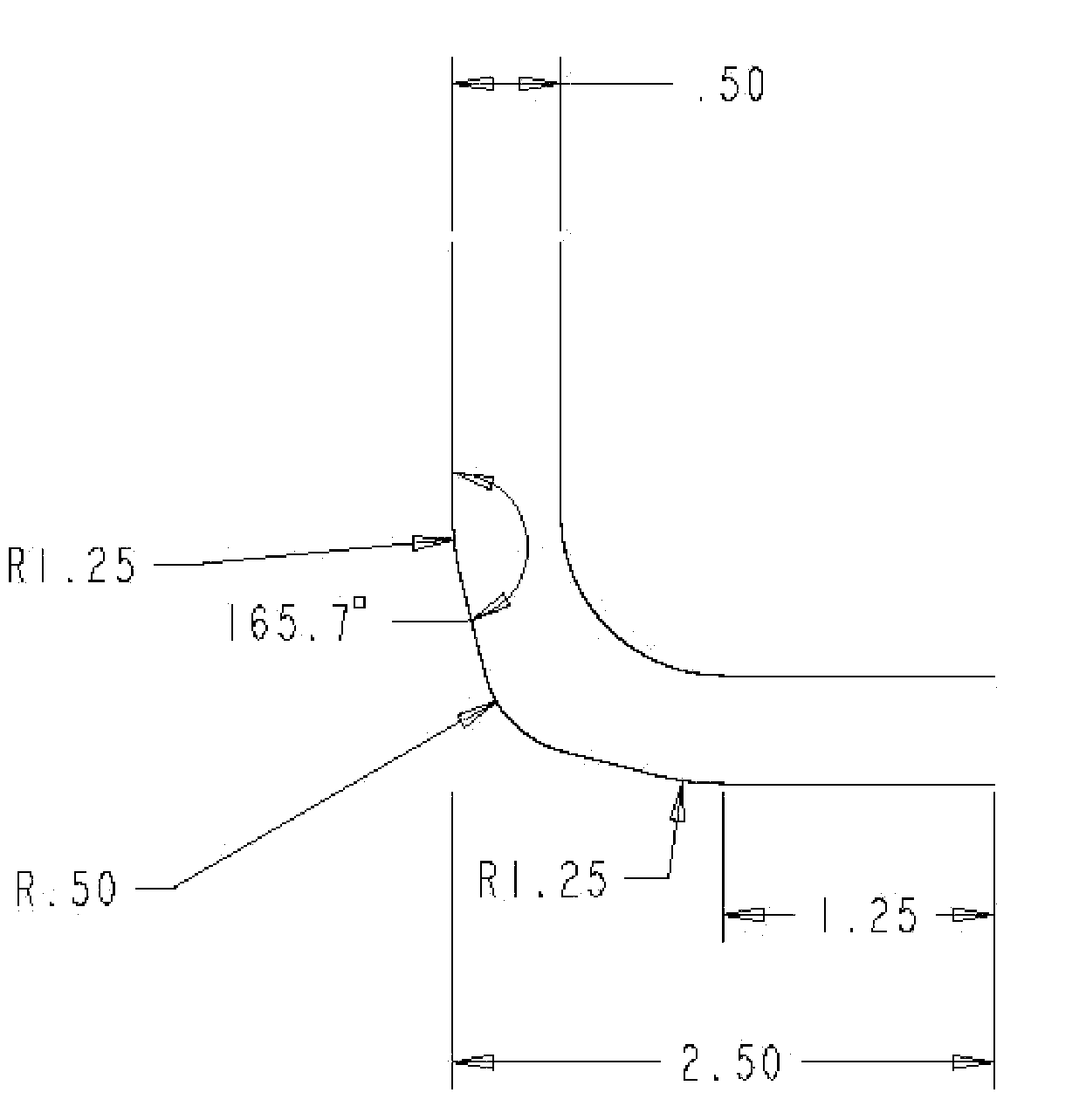
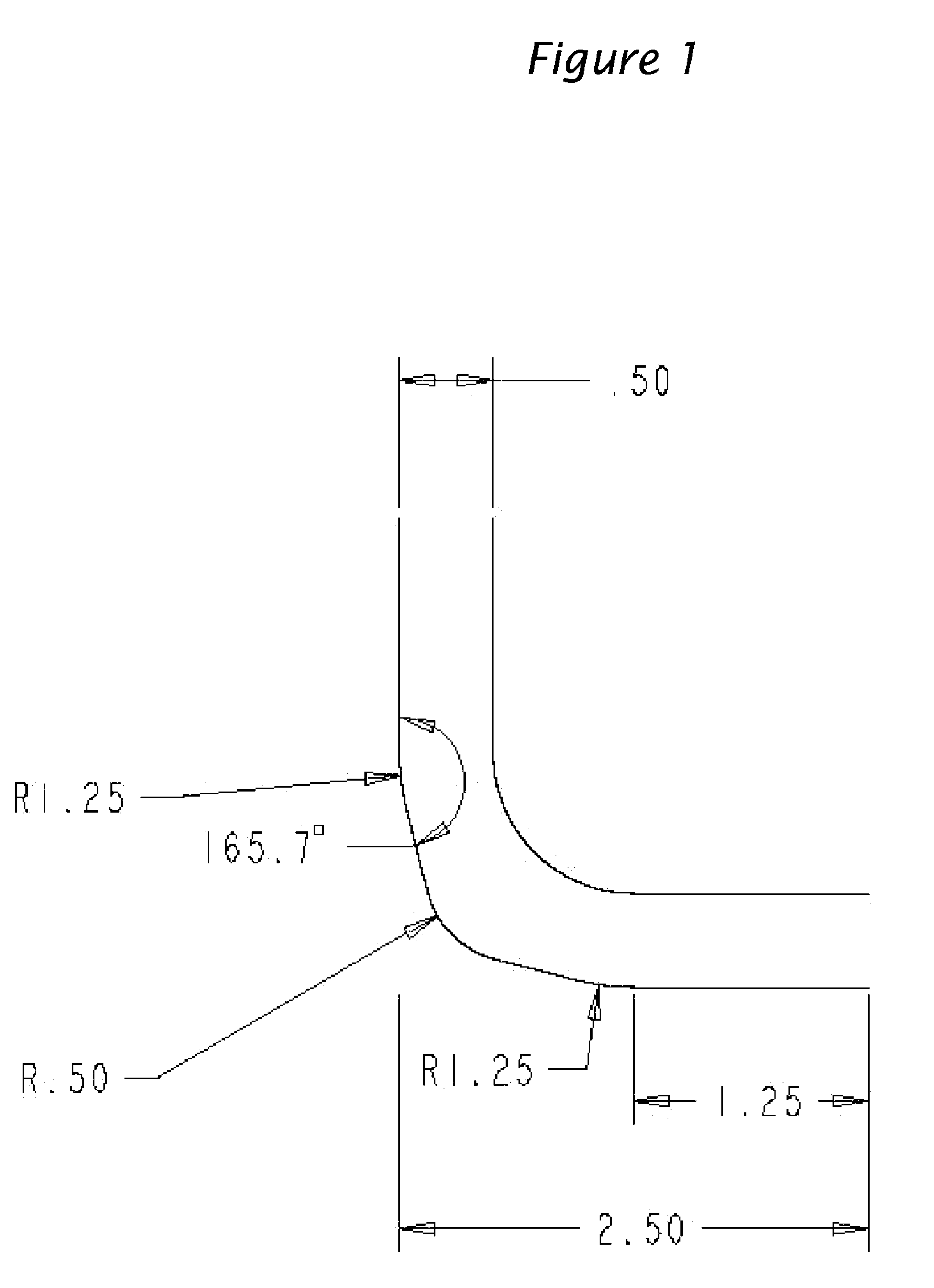
[0030]A honeycomb having a corner as shown in FIG. 1, which has two equal circular radii, two straight chamfers and one different circular radius, was modeled using finite element analysis using an axisymetric 45 degree model, 8 node plane strain elements under a 45 degree load of 1 N / mm of length of the honeycomb. The units in FIG. 1 are in millimeters. The material properties were chosen to reflect typical ceramic material properties, which were material modulus of 30,000 MPa and a Poisson's ratio of 0.25. The maximum stress under the applied load at the corner was 32.8 MPa and this maximum load was shifted away from the midway point of the corner at the surface of the wall in the channel.

example 2

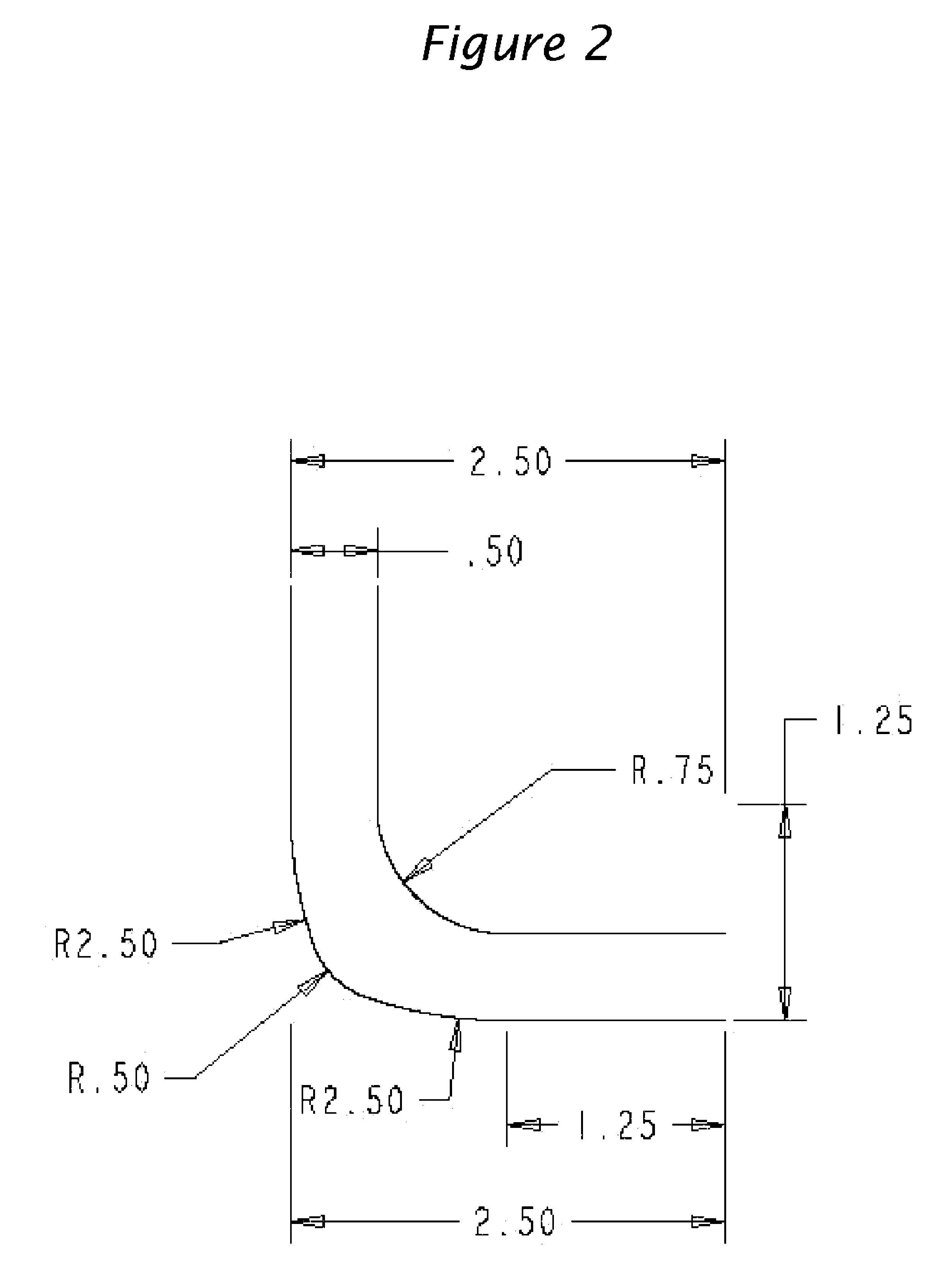
[0031]A honeycomb having a corner as shown in FIG. 2, which has two equal circular radii and one different circular radius, was modeled as above using the same material constants. The maximum stress under the applied load at the corner was 30.6 MPa and this maximum load was shifted from the midway point of the corner at the surface of the wall in the channel.


PUM

PropertyMeasurementUnit
porosityaaaaaaaaaa
porosityaaaaaaaaaa
porosityaaaaaaaaaa

Abstract

An improved ceramic honeycomb filter wherein the ceramic honeycomb filter has at least one outer corner having a shape, when viewed looking down the channels of the honeycomb, that is comprised of (i) at least two circular arcs wherein at least one of said circular arcs has a different radius of curvature than the other circular arc or arcs, (ii) a non-circular arc, or (iii) at least four straight chamfers in the absence of any arcs.

Description

CROSS-REFERENCE TO RELATED APPLICATION[0001]This application claims the benefit of US Provisional Patent Application 60 / 927,653.FIELD OF THE INVENTION[0002]The present invention relates to an improved ceramic honeycomb particulate filter. In particular, the invention relates to extruding honeycomb ceramic filters that have improved strength and improved resistance to handling damage.BACKGROUND OF THE INVENTION[0003]Diesel engines, because of the way they operate, emit soot particles or very fine droplets of condensate or a conglomerate of the two (particulates) as well as typical harmful gasoline engine exhausts (i.e., HC and CO). These “particulates” (herein Diesel soot), are rich in condensed, polynuclear hydrocarbons, some of which may be carcinogenic.[0004]As the awareness of the danger Diesel soot presents to health collides with the need for greater fuel efficiency that Diesel engines provide, regulations have been enacted curbing the amount of Diesel soot permitted to be emit...

Claims


Application Information

Patent Timeline
Patent Type & Authority Patents(United States)
IPC IPC(8): B01D46/00
CPCB01D46/2429B01D46/2451B01D46/2455F01N3/0222B01D46/2425B01D2046/2496B01D2279/30F01N2330/30Y02T10/20Y10S55/30Y02T10/12B01D46/2498B01D46/24B01D39/00B01J35/04F01N3/022B01D46/2486
Inventor ZAWISZA, JEFFERY D.
Owner DOW GLOBAL TECH LLC
Why Eureka
Try Eureka