Secondary battery and battery pack

Active Publication Date: 2019-08-15
TOYOTA JIDOSHA KK
View PDF2 Cites 2 Cited by
  • Summary
  • Abstract
  • Description
  • Claims
  • Application Information

AI Technical Summary

Benefits of technology

The present disclosure aims to relieve tensile stress on an insulating film in a secondary battery caused by the expansion of the wound electrode body without creating excessive space between the lower end of the wound electrode body and the insulating film. By positioning grooves between two planes and allowing the insulating film to bend along the grooves, the space between the wound electrode body and the insulating film is reduced, resulting in improved battery performance and reduced dead space. This configuration balances productivity and suppression of dead space, and allows for excellent formability of the insulating film.

Problems solved by technology

When the bag-shaped insulating film is of square type, as disclosed in Japanese Patent Application Publication No. 2016-219143 and Japanese Patent Application Publication No. 2011-198663, the insulating film is prone to colliding with the top end portion of the battery case during an insertion operation.
In order to prevent such a collision, the distance between the bottom of the battery case and the insulating film must be increased, which translates into a dead space.
In the battery pack, however, the portions of the insulating film in contact with the flat portion of the wound electrode body are fixed in the manner described above, and accordingly the region over which the insulating film can extend is small, and tensile stress is not relieved readily.
Upon repeated expansion and contraction of the wound electrode body, therefore, tensile stress repeatedly acts on the bottom portion of the insulating film, and deterioration of the insulating film is accelerated as a result, which is problematic.
This space is a dead space and entails a drop in battery capacity.
Further, that space might hinder the return, to the wound electrode body, of electrolyte solution released from the wound electrode body.
Particular problems arise thus when the secondary battery is used while restrained, for instance as a battery pack.

Method used


Image

  • Secondary battery and battery pack
  • Secondary battery and battery pack
  • Secondary battery and battery pack

Examples


Embodiment Construction

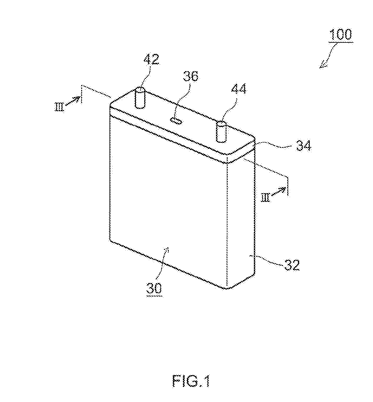
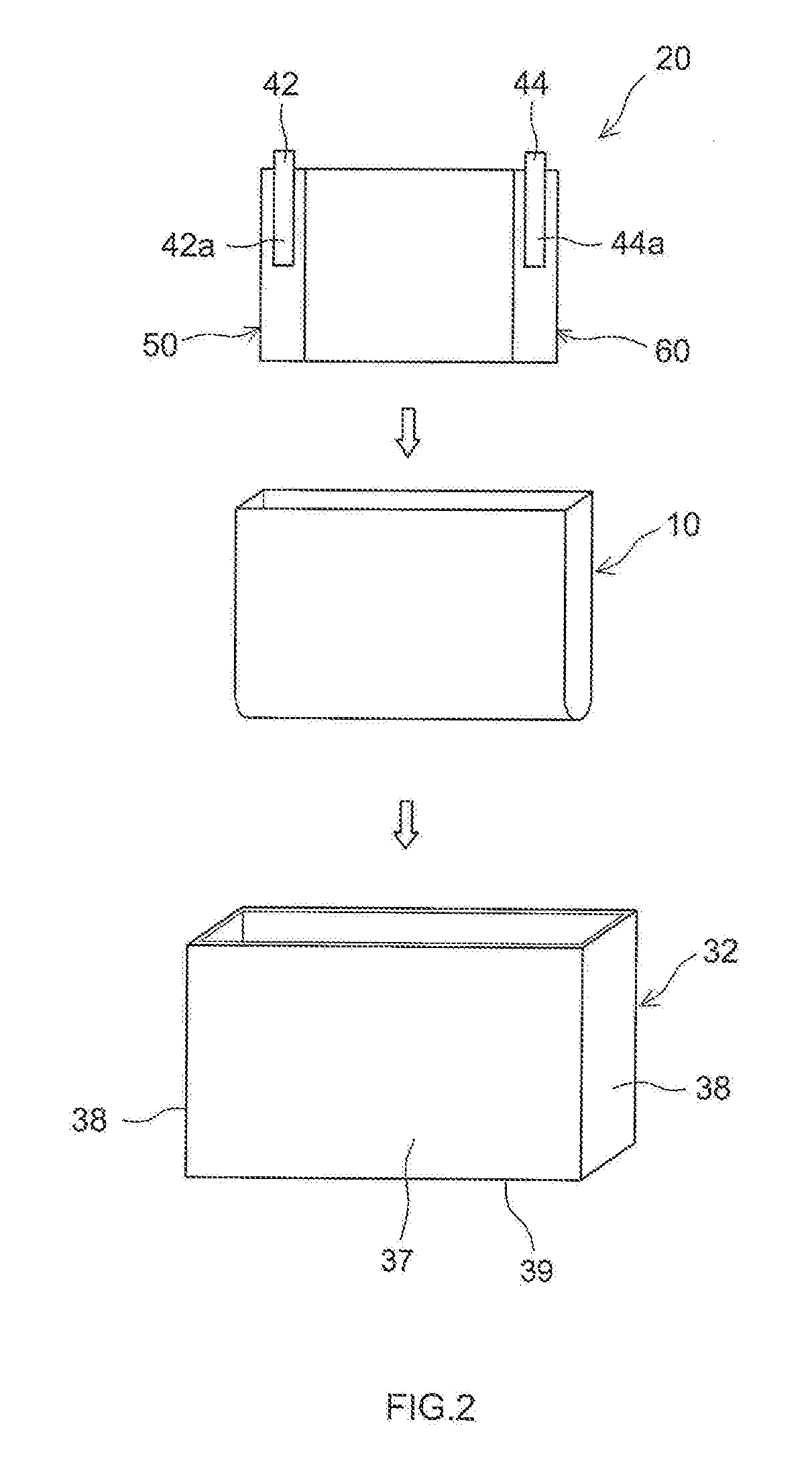
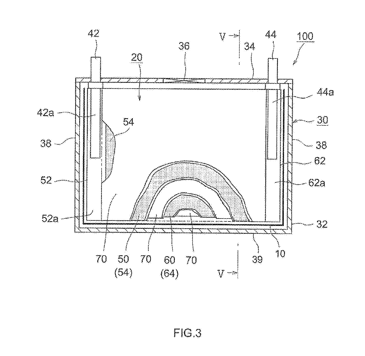
[0043]Embodiments of the present disclosure will be explained below with reference to accompanying drawings. Any features other than the matter specifically set forth in the present specification and that may be necessary for carrying out the present disclosure (for instance, the ordinary configuration and production process of a secondary battery and a battery pack, not being characterizing features of the present disclosure) can be regarded as instances of design matter, for a person skilled in the art, based on known techniques in the relevant technical field. The present disclosure can be realized on the basis of the disclosure of the present specification and common technical knowledge in the relevant technical field. In the drawings below, members and portions that elicit identical effects are denoted with identical reference symbols. The dimensional relationships (length, width, thickness and so forth) in the figures do not reflect actual dimensional relationships.

[0044]In th...


PUM


Abstract

A secondary battery includes a flat wound electrode body; a battery case that accommodates the wound electrode body; and an insulating film. The wound electrode body has a first radius section opposing a top surface of the battery case, a second radius section opposing a bottom surface of the battery case, and a flat portion flanked by the first radius section and the second radius section. The insulating film is disposed between a flat surface of the flat portion of the wound electrode body and the battery case, and between a curved surface of the second radius section of the wound electrode body and the battery case. The insulating film has one groove at a portion opposing the curved surface of the second radius section and positioned between two planes resulting from extending two flat surfaces of the wound electrode body.

Description

CROSS-REFERENCE TO RELATED APPLICATIONS[0001]The present application claims priority to Japanese Patent Application No. 2018-021952 filed on Feb. 9, 2018, the entire contents of which are incorporated into the present specification by reference.BACKGROUND1. Technical Field[0002]The present disclosure relates to a secondary battery. More particularly, the present disclosure relates to a secondary battery that is used while restrained. The present disclosure relates also to a battery pack.2. Description of the Related Art[0003]In recent years, secondary batteries such as lithium ion secondary batteries have come to be suitably used as portable power sources in personal computers, mobile terminals and the like, and as power sources for vehicle drive in electric vehicles (EV), hybrid vehicles (HV) and plug-in hybrid vehicles (PHV).[0004]Secondary batteries such as lithium ion secondary batteries have typically a configuration wherein an electrode body provided with a positive electrode ...

Claims


Application Information

Patent Timeline
IPC IPC(8): H01M10/0587
CPCH01M10/0587H01M2220/20H01M10/0525H01M4/131H01M50/10H01M50/20H01M10/0431Y02E60/10Y02P70/50H01G11/82H01M50/572H01M2220/30Y02T10/70
Inventor YAMANE, SHINGO
Owner TOYOTA JIDOSHA KK
Why Eureka
Try Eureka