Sounding reference signal antenna switching in scheduled entities having at least four antennas

a reference signal and antenna switching technology, applied in diversity/multi-antenna systems, wireless communication, transmission path division, etc., can solve the problems of less than adequate sounding procedure and configuration of srs from those earlier standards

Active Publication Date: 2019-08-15
QUALCOMM INC
View PDF2 Cites 30 Cited by
  • Summary
  • Abstract
  • Description
  • Claims
  • Application Information

AI Technical Summary

Benefits of technology

The technical effect of this patent is to describe various aspects of a new technology without providing exhaustive details about each aspect. It provides a brief introduction to the main ideas involved in these technologies.

Problems solved by technology

This patent discusses how a sounding reference signal (SRS) is used in wireless communication systems to measure the quality of the uplink carriers and adjust communication signals accordingly. However, there are some technical challenges when applying this method in 5G networks due to differences in frequency ranges, timings, and transmission methods compared to previous generations. Therefore, research continues to develop better ways to utilize SRS in advanced wireless communication technology.

Method used


Image

  • Sounding reference signal antenna switching in scheduled entities having at least four antennas
  • Sounding reference signal antenna switching in scheduled entities having at least four antennas
  • Sounding reference signal antenna switching in scheduled entities having at least four antennas

Examples


Embodiment Construction

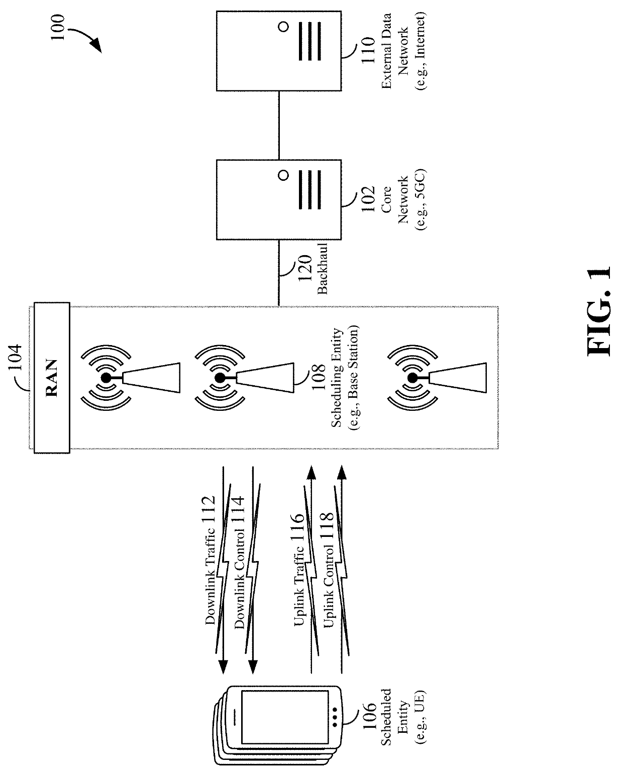
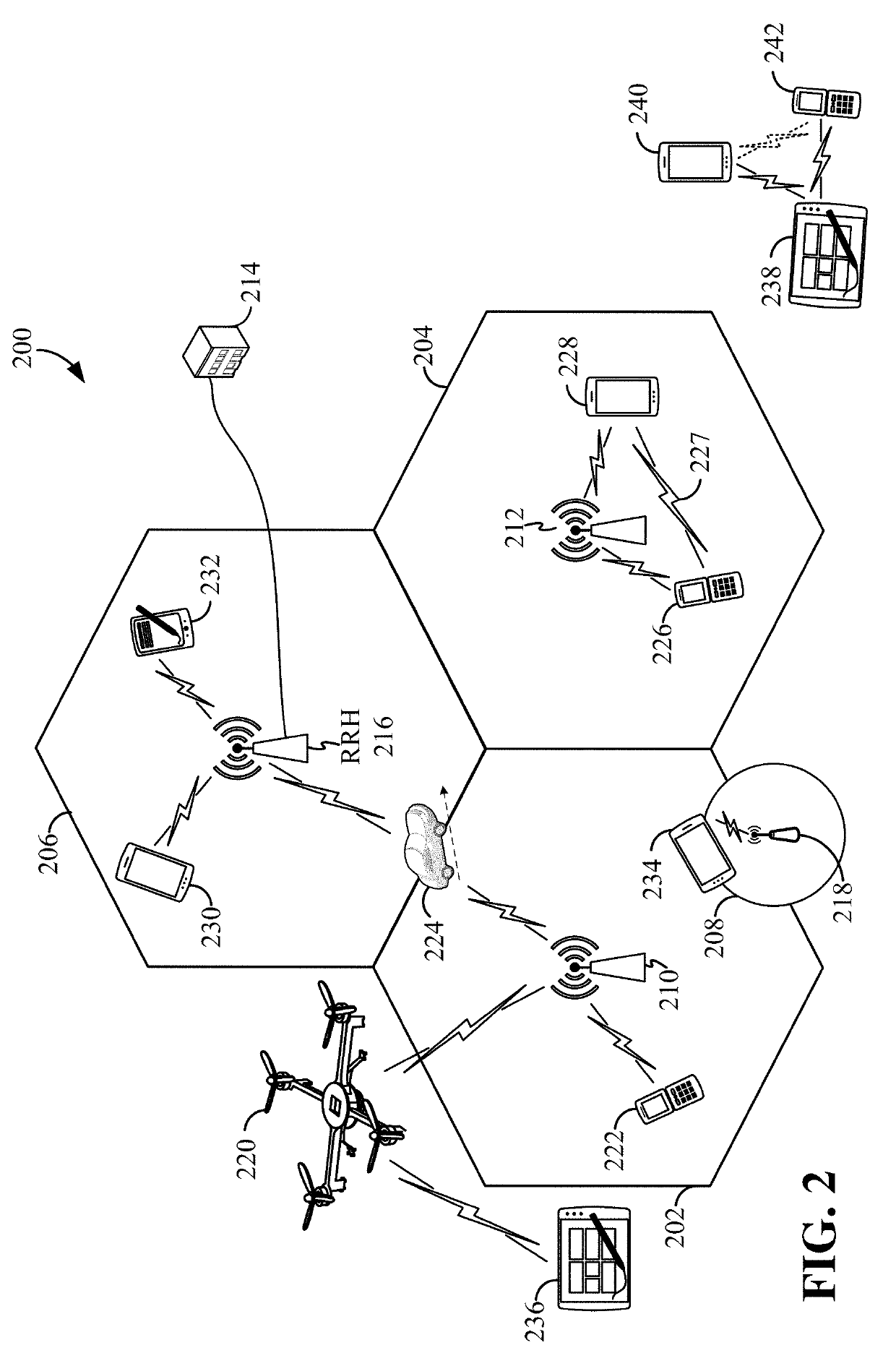
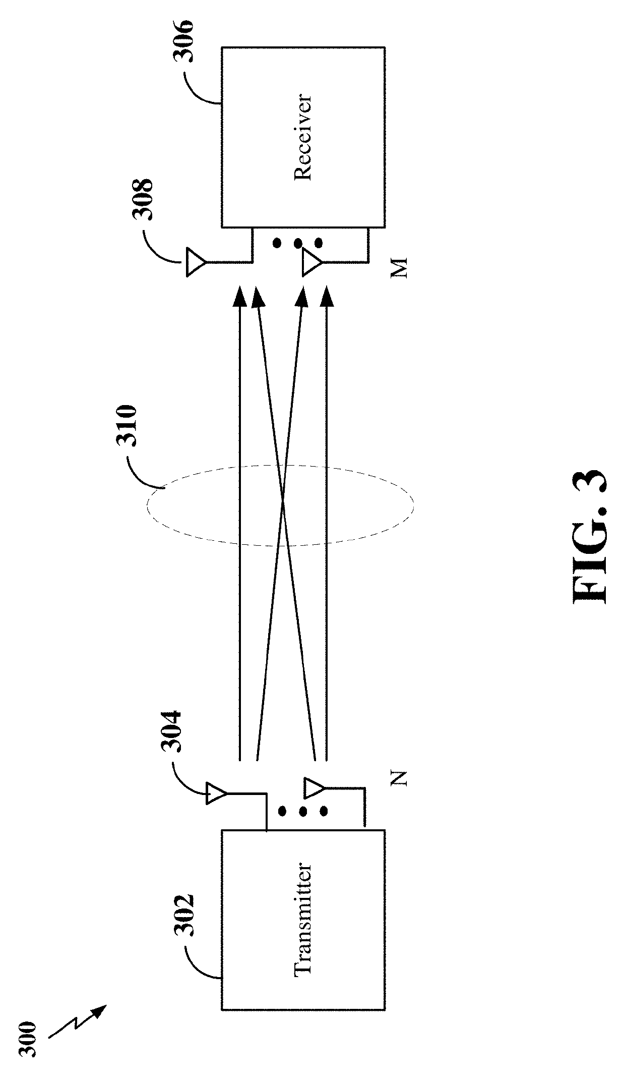
[0050]The detailed description set forth below in connection with the appended drawings is intended as a description of various configurations and is not intended to represent the only configurations in which the concepts described herein may be practiced. The detailed description includes specific details for the purpose of providing a thorough understanding of various concepts. However, it will be apparent to those skilled in the art that these concepts may be practiced without these specific details. In some instances, well known structures and components are shown in block diagram form in order to avoid obscuring such concepts.

[0051]While aspects and embodiments are described in this application by illustration to some examples, those skilled in the art will understand that additional implementations and use cases may come about in many different arrangements and scenarios. Innovations described herein may be implemented across many differing platform types, devices, systems, sh...


PUM


Abstract

Aspects directed towards sounding reference signal (SRS) antenna switching are disclosed. In one example, an SRS configuration is received from a network in which at least four antennas of a scheduled entity are configured based on the SRS configuration. Here, the SRS configuration configures at least one antenna to simultaneously support SRS antenna switching and an uplink (UL) multiple-input multiple-output (MIMO) communication. An SRS communication is then transmitted according to the SRS configuration. In another example, a transmission capability reporting is received from a scheduled entity comprising at least four antennas. A determination is then made of whether the scheduled entity may simultaneously support SRS antenna switching and an UL MIMO communication. An SRS configuration is then generated for the scheduled entity based on the determination in which a default SRS configuration configures at least one antenna to simultaneously support the SRS antenna switching and the UL MIMO communication.

Description


Claims


Application Information

Patent Timeline
Owner QUALCOMM INC
Why Eureka
Try Eureka