Method and device of power control

a power control and power technology, applied in power management, vehicle components, network traffic/resource management, etc., can solve the problems that the d2d functions that have been already implemented are far from meeting the user's requirements, and achieve the effect of ensuring the transmission efficiency of v2x and the transmission of uu uplink

Active Publication Date: 2019-08-15
SAMSUNG ELECTRONICS CO LTD
View PDF1 Cites 17 Cited by
  • Summary
  • Abstract
  • Description
  • Claims
  • Application Information

AI Technical Summary

Benefits of technology

[0040]The present disclosure provides a method and a device of power control, for a Uu uplink transmission and a V2X transmission. Specifically, the present disclosure provides a method for determining the transmission power based on the circumstance of synchronous/asynchronous car

Problems solved by technology

Since the D2D communication specified in the 3GPP standards is mainly focused on terminals with low speeds and services that is not sensitive to

Method used


Image

  • Method and device of power control
  • Method and device of power control
  • Method and device of power control

Examples


first example

A First Example

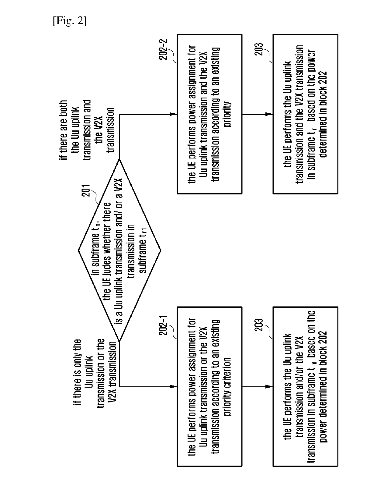
[0079]FIG. 2 is a flowchart of the present application.

[0080]In block 201, in subframe tn, the UE judges whether there is a Uu uplink transmission and / or a V2X transmission in subframe tn1. If there is only the Uu uplink transmission or the V2X transmission, proceed to block 202-1. If there are both the Uu uplink transmission and the V2X transmission, proceed to block 202-2. If there is none of them, the UE does not need to perform any operation.

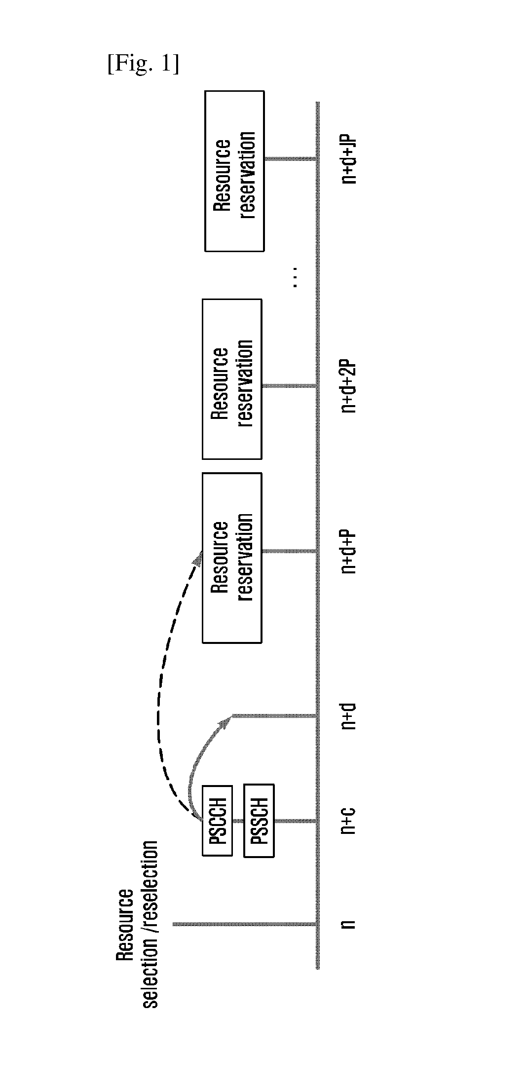
[0081]Wherein, subframe tn1 is the subframe where the UE transmits the Uu uplink data or the V2X transmission. Subframe tn is a time point of the UE starting preparing the power of the Uu uplink data scheduled or a time point of the UE starting preparing the V2X transmission power. Subframe tn is before subframe tn1, and a time difference X5 is larger than or equal to the minimum time delay Y1 or Y3 of adjusting power.

[0082]In some examples, the carrier used for the V2X transmission and the carrier used for the Uu uplink trans...

second example

A Second Example

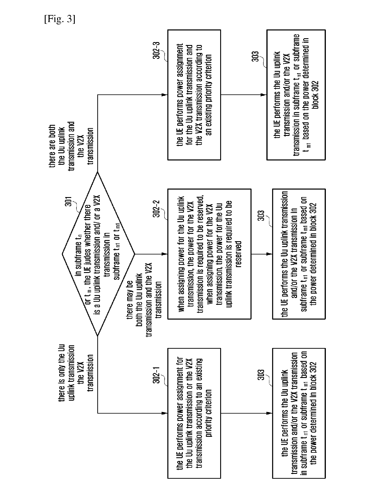
[0109]FIG. 3 is a flowchart of the present application.

[0110]In block 301, in subframe tn or tm, the UE judges whether there is a Uu uplink transmission and / or a V2X transmission in subframe tn1 or tm1. If it is certain that there is only the Uu uplink transmission or the V2X transmission, proceed to block 302-1. If there are potentially both the Uu uplink transmission and the V2X transmission, proceed to block 302-2. If it is certain that there are both the Uu uplink transmission and the V2X transmission, proceed to block 302-3. The block 302-3 is carried out in accordance with the block 202-2 in the first example, or in accordance with the method described in this example. If there is none of them, the UE does not need to perform any operation.

[0111]Wherein, subframe tn1 is the subframe where the UE transmits the Uu uplink data, and subframe tm1 is the subframe where the UE transmits the V2X transmission. Subframe tn is a time point of the UE starting preparing the...

third example

A Third Example

[0184]FIG. 4 is a flowchart of the present application.

[0185]The example applies to the case that the V2X carrier is synchronized with the Uu uplink carrier, and is also applicable to non synchronization case.

[0186]A major difference from the second example is that the V2X power is assigned differently.

[0187]In some examples, if the minimum time delay X1 from the arriving of the V2X service to the transmitting of the PSCCH / PSSCH on the selected resource in V2X communication is smaller than the minimum delay X3 required by the UE for preparing the uplink transmission PUSCH in Uu communication (further, in specific implementations, it may be that the minimum time delay Y1 of the UE adjusting the PSCCH / PSSCH transmission power in V2X communication is smaller than the minimum delay Y3 required by the UE preparing the uplink transmission PUSCH in Uu communication), the UE may accurately determine there is the Uu uplink transmission in the same subframe when determining the...


PUM


Abstract

The present disclosure relates to a communication method and system for converging a 5th-Generation (5G) communication system for supporting higher data rates beyond a 4th-Generation (4G) system with a technology for Internet of Things (IoT). The present disclosure may be applied to intelligent services based on the 5G communication technology and the IoT-related technology, such as smart home, smart building, smart city, smart car, connected car, health care, digital education, smart retail, security and safety services. The present disclosure provides a method and a device of power control for a Uu uplink transmission and a V2X transmission. Specifically, the present disclosure provides a method for determining the transmission power based on the circumstance of synchronous/asynchronous carriers, a minimum time delay of preparing the transmission power of the V2X and Uu uplink transmission, and an actual time delay of V2X from a resource reselection to a transmission. By this method, the transmission efficiency of the V2X and the Uu uplink transmission can be ensured.

Description

TECHNICAL FIELD[0001]The present application relates to wireless communication technologies, in particular to a method and a device for determining the transmission power in V2X systems.BACKGROUND ART[0002]To meet the demand for wireless data traffic having increased since deployment of 4G communication systems, efforts have been made to develop an improved 5G or pre-5G communication system. Therefore, the 5G or pre-5G communication system is also called a ‘Beyond 4G Network’ or a ‘Post LTE System’. The 5G communication system is considered to be implemented in higher frequency (mmWave) bands, e.g., 60 GHz bands, so as to accomplish higher data rates. To decrease propagation loss of the radio waves and increase the transmission distance, the beamforming, massive multiple-input multiple-output (MIMO), Full Dimensional MIMO (FD-MIMO), array antenna, an analog beam forming, large scale antenna techniques are discussed in 5G communication systems. In addition, in 5G communication system...

Claims


Application Information

Patent Timeline
IPC IPC(8): H04W52/14H04W52/28H04W52/36H04W52/16H04W72/04H04W72/10
CPCH04W52/146H04W52/281H04W72/10H04W52/16H04W72/0473H04W52/367H04W28/0215H04W28/0221H04W52/383H04W4/40H04L47/28H04W40/22H04W72/56
Inventor WANG, YILI, YINGYANGZHANG, SHICHANG
Owner SAMSUNG ELECTRONICS CO LTD
Why Eureka
Try Eureka