Sphygmomanometer, blood pressure measurement method, and device

Pending Publication Date: 2019-09-26
ORMON CORP +1
View PDF0 Cites 0 Cited by
  • Summary
  • Abstract
  • Description
  • Claims
  • Application Information

AI Technical Summary

Benefits of technology

[0009]Therefore, an object of the present invention is to provide a sphygmomanometer, a blood pressure measurement method, and a device that are capable of accu

Problems solved by technology

However, in the sphygmomanometer described above, if the width direction dimension of the cuff is set to be as small as, for example, 25 mm, the cuff (air bag) greatly inflates in the thickness direction when pressurized, and its cross section becomes

Method used


Image

  • Sphygmomanometer, blood pressure measurement method, and device
  • Sphygmomanometer, blood pressure measurement method, and device
  • Sphygmomanometer, blood pressure measurement method, and device

Examples


Example

[0069]Hereinafter, embodiments of the present invention will be described in detail with reference to the drawings.

(Configuration of Sphygmomanometer)

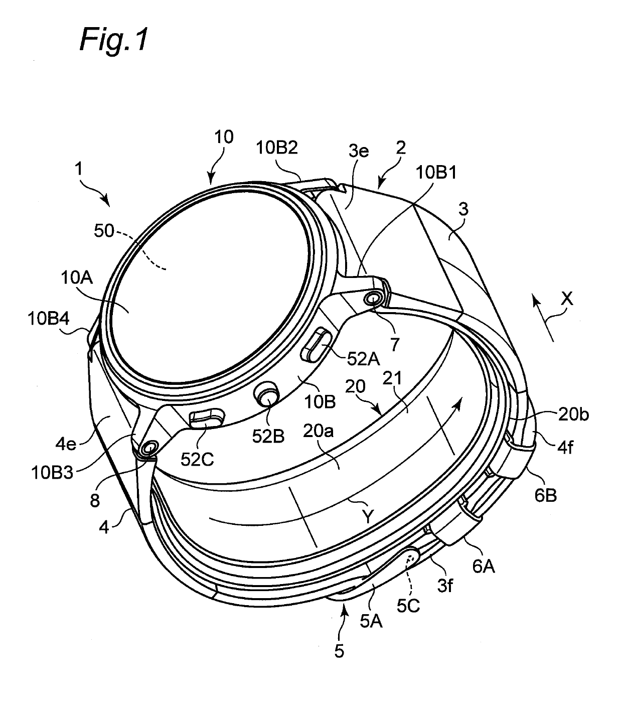
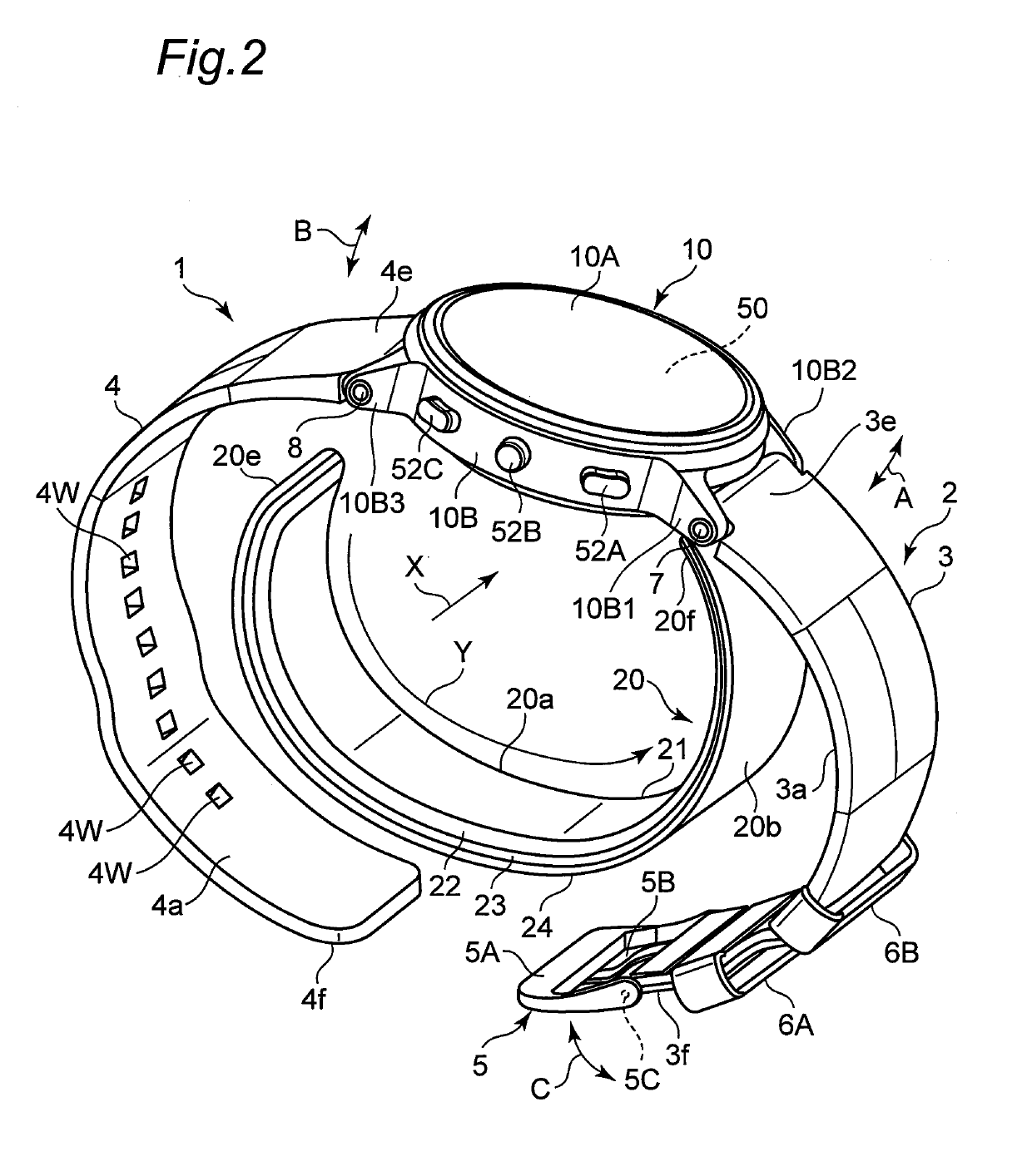
[0070]FIG. 1 shows an appearance of a sphygmomanometer according to an embodiment of the present invention (indicated by a reference numeral 1 as a whole) as viewed obliquely, with a belt 2 fastened. FIG. 2 shows the appearance of the sphygmomanometer 1 as viewed obliquely, with the belt 2 released.

[0071]As shown in these figures, the sphygmomanometer 1 roughly includes a main body 10, the belt 2 which extends from the main body 10 and is to be attached around a measurement target site (in this example, as shown in FIG. 13C described later, a left wrist 90 is assumed to be the measurement target site), and a cuff structure 20 that has a band shape and has one end 20f attached to the main body 10. The dimension of the belt 2 in a width direction X is set to 29 mm in this example. The thickness of the belt 2 is set to 2 mm in this exampl...


PUM


Abstract

A sphygmomanometer according to the present invention includes a main body mounted with a pump, a belt, and a cuff structure. The cuff structure having a band shape is disposed facing an inner circumferential surface of the belt and has one end attached to the main body in a freely separable manner from the inner circumferential surface of the belt. The cuff structure includes a bag-shaped pressure cuff that extends along a circumferential direction of a measurement target site, a bag-shaped sensing cuff that extends in the circumferential direction across an artery passing portion of the measurement target site, and a back plate that is inserted between the pressure cuff and the sensing cuff. A pressurization fluid is supplied from the pump to the pressure cuff to press the measurement target site. A blood pressure is calculated based on a pressure of a pressure transmission fluid contained in the sensing cuff.

Description

CROSS-REFERENCE TO RELATED APPLICATION[0001]This is a continuation application of International Application No. PCT / JP2017 / 042085, with an International filing date of Nov. 22, 2017, which claims priority of Japanese Patent Application No. 2016-256022 filed on Dec. 28, 2016, the entire content of which is hereby incorporated by reference.TECHNICAL FIELD[0002]The present invention relates to a sphygmomanometer, and more particularly to a sphygmomanometer including a belt attached around a measurement target site and a main body mounted with a pump. The present invention also relates to a blood pressure measurement method for measuring a blood pressure at a measurement target site. Furthermore, the present invention relates to a device including a blood pressure measurement function.BACKGROUND ART[0003]Conventionally, as this type of sphygmomanometer, for example, as disclosed in Patent Literature 1 (JP 2013-215397 A), there is known a sphygmomanometer having a blood pressure measurem...

Claims


Application Information

Patent Timeline
IPC IPC(8): A61B5/022A61B5/021A61B5/00
CPCA61B5/02225A61B5/02108A61B5/0235A61B2562/0219A61B5/02141A61B5/681A61B5/02233A61B2562/0247A61B5/022
Inventor HIGASHIMURA, YUBRIGHAM, BRIANESHITA, SHUSUKENISHIOKA, TAKANORISANO, YOSHIHIKOKUBO, TAKESHI
Owner ORMON CORP
Why Eureka
Try Eureka