Blood pressure monitoring apparatus

a monitoring apparatus and blood pressure technology, applied in the field of blood pressure monitoring apparatus, can solve the problems of complicated measurement, non-continuous measurement, and inability to continuously monitor blood pressure, and achieve the effect of accurate measurement of blood pressur

Active Publication Date: 2007-03-22
FUKUDA DENSHI CO LTD
View PDF7 Cites 134 Cited by
  • Summary
  • Abstract
  • Description
  • Claims
  • Application Information

AI Technical Summary

Benefits of technology

[0013] The present invention has been made in consideration of the problems of the prior art as described above, and has as its object to make it possible to accurately measure the blood pressure in a blood pressure monitoring apparatus which continuously estimates the blood pressure on the basis of the pulse wave propagation time.

Problems solved by technology

However, but these measurements are generally not continuous measurements.
On the other hand, in places such as an operating room and ICU for treating serious patients, continuous blood pressure monitoring is sometimes necessary.
To measure the pulse wave propagation time, however, pulse waves must be measured in two different locations of the body, so the measurement is complicated.
Also, injuries of the patient or interferences with another medical tool sometimes make it difficult to attach sensors or cuffs for measuring pulse waves to the measurement locations.
Unfortunately, the use of an ECG in the calculation of the pulse wave propagation time has a demerit that the measurement accuracy of the pulse wave propagation time decreases.
Therefore, the accuracy improvement by the correction is limited.
However, this method requires avascularization, so the frequent use of the method is undesirable because the burden on a patient increases.
If the threshold values are too moderate, however, an abnormality of the true blood pressure also becomes difficult to detect, and this makes appropriate threshold values very difficult to set.

Method used


Image

  • Blood pressure monitoring apparatus
  • Blood pressure monitoring apparatus
  • Blood pressure monitoring apparatus

Examples


Embodiment Construction

[0023] Preferred embodiments of the present invention will now be described in detail in accordance with the accompanying drawings.

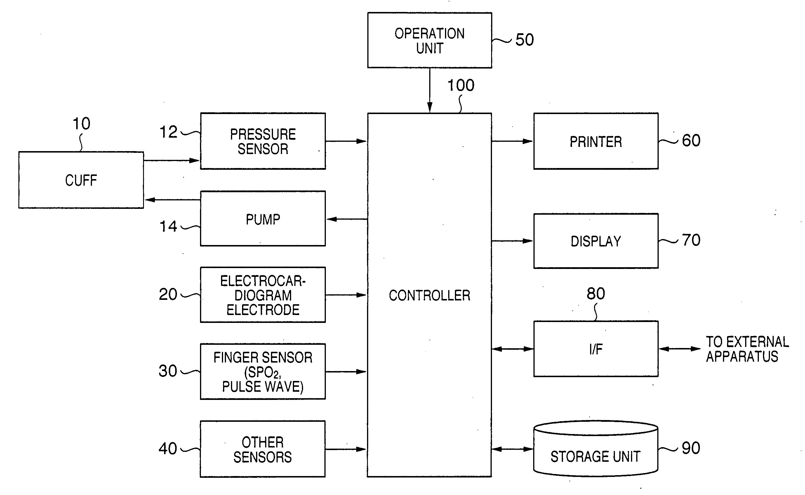
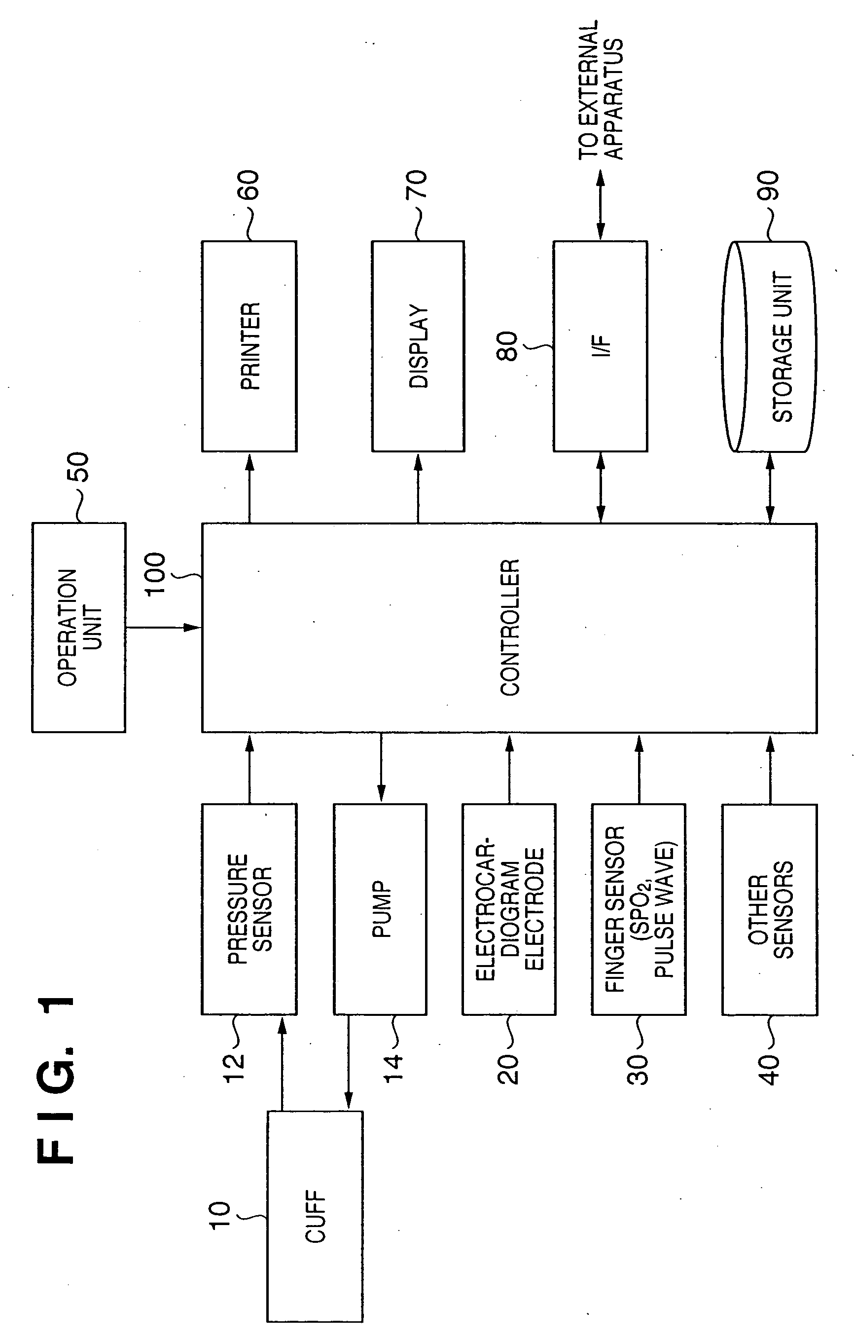
[0024]FIG. 1 is a block diagram showing an example of the functional configuration of a biological information monitoring apparatus as a blood pressure monitoring apparatus according to an embodiment of the present invention.

[0025] Referring to FIG. 1, a cuff 10 has a band-like shape, and incorporates a rubber bladder which inflates and deflates by charging and evacuating of a gas by a pump 14. The cuff 10 is normally attached to one of the limbs, typically the upper arm of a patient. A pressure sensor 12 senses a change in pressure applied to the gas filled in the internal rubber bladder of the cuff 10, converts the pressure signal into an electrical signal, and outputs the electrical signal to a controller 100.

[0026] An electrocardiogram electrode 20 comprising a plurality of electrodes is attached to a predetermined position of the chest of a patie...


PUM


Abstract

A blood pressure monitoring apparatus which continuously estimates and monitors the blood pressure by using the pulse wave propagation time can accurately estimate the blood pressure. While an estimated blood pressure is continuously calculated by using the pulse wave propagation time, the correlation between the pulse wave propagation time and the interval between feature points contained in two consecutive heart beat waveforms of an electrocardiogram is monitored. If the correlation is reversed, the blood pressure is actually measured, and the estimated blood pressure is corrected on the basis of the difference between the estimated blood pressure and actually measured blood pressure.

Description

CLAIM OF PRIORITY [0001] This application claims priority from Japanese Patent Application No. 2005-273877, filed on Sep. 21, 2005, which is hereby incorporated by reference herein. BACKGROUND OF THE INVENTION [0002] 1. Field of the Invention [0003] The present invention relates to a blood pressure monitoring apparatus for noninvasively and continuously monitoring blood pressure. [0004] 2. Description of the Related Art [0005] There are many opportunities for measuring blood pressure for purposes such as a medical examination, a diagnosis of a disease, and daily physical condition check-up. However, but these measurements are generally not continuous measurements. On the other hand, in places such as an operating room and ICU for treating serious patients, continuous blood pressure monitoring is sometimes necessary. An apparatus using blood pressure estimation based on the pulse wave propagation time is conventionally known as a blood pressure monitoring apparatus for noninvasively ...

Claims


Application Information

Patent Timeline
Patent Type & Authority Applications(United States)
IPC IPC(8): A61B5/04A61B5/02
CPCA61B5/02125A61B5/0285A61B5/02233A61B5/02141
Inventor INUKAI, HIDEKATSUOKA, TORU
Owner FUKUDA DENSHI CO LTD
Why Eureka
Try Eureka