Apparatus and process for producing co2 enriched medical foam

Active Publication Date: 2019-09-26
LEVY FRANK
View PDF0 Cites 0 Cited by
  • Summary
  • Abstract
  • Description
  • Claims
  • Application Information

AI Technical Summary

Benefits of technology

[0012]In a preferred embodiment, the CO2 gas that is expelled from the apparatus will ultimately be used for foaming of medical solutions to produce a CO2 enriched foam for the healing of ulcerations. These solutions may include, but would not be limited to saline, aloe, Amerigel®, microbial agents, and surfactants. CO2 is used to aerate the

Problems solved by technology

The limiting case of the Venturi effect is choked flow, in which a constriction in a pipe or channel limits the total flow rate through

Method used


Image

  • Apparatus and process for producing co2 enriched medical foam
  • Apparatus and process for producing co2 enriched medical foam
  • Apparatus and process for producing co2 enriched medical foam

Examples


Embodiment Construction

[0019]Other objects, features and advantages will occur from the following description of a preferred embodiment and the accompanying drawings, in which:

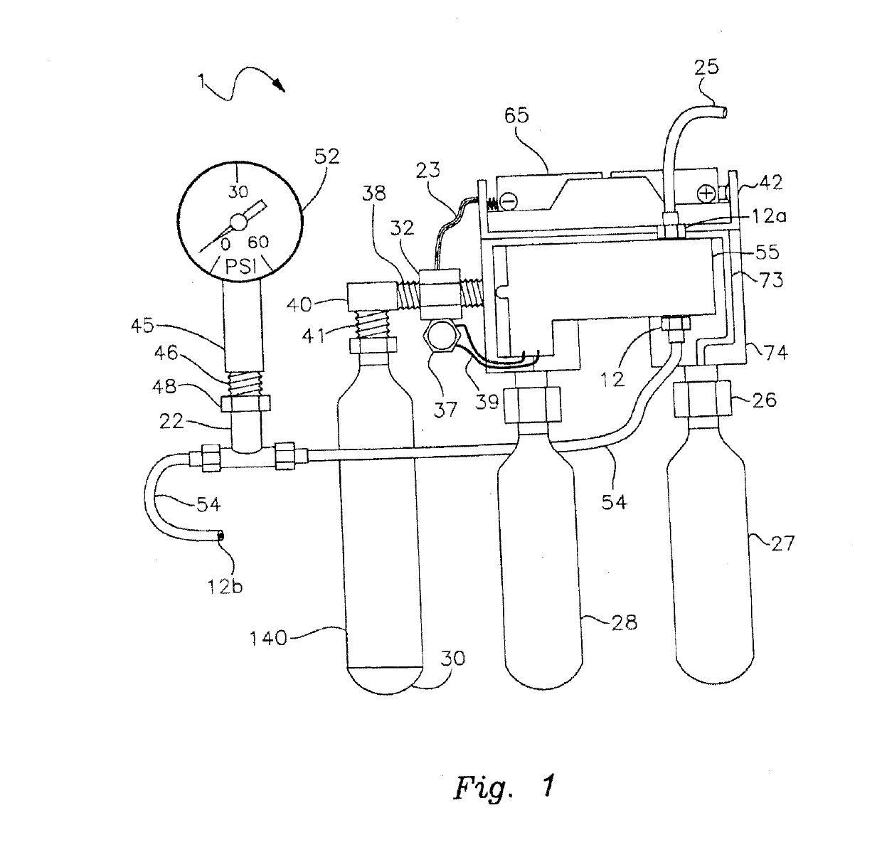
[0020]FIG. 1 is a side perspective and partly schematic view of an apparatus including compressed gas (CO2) cylinders and a solenoid of the present invention;

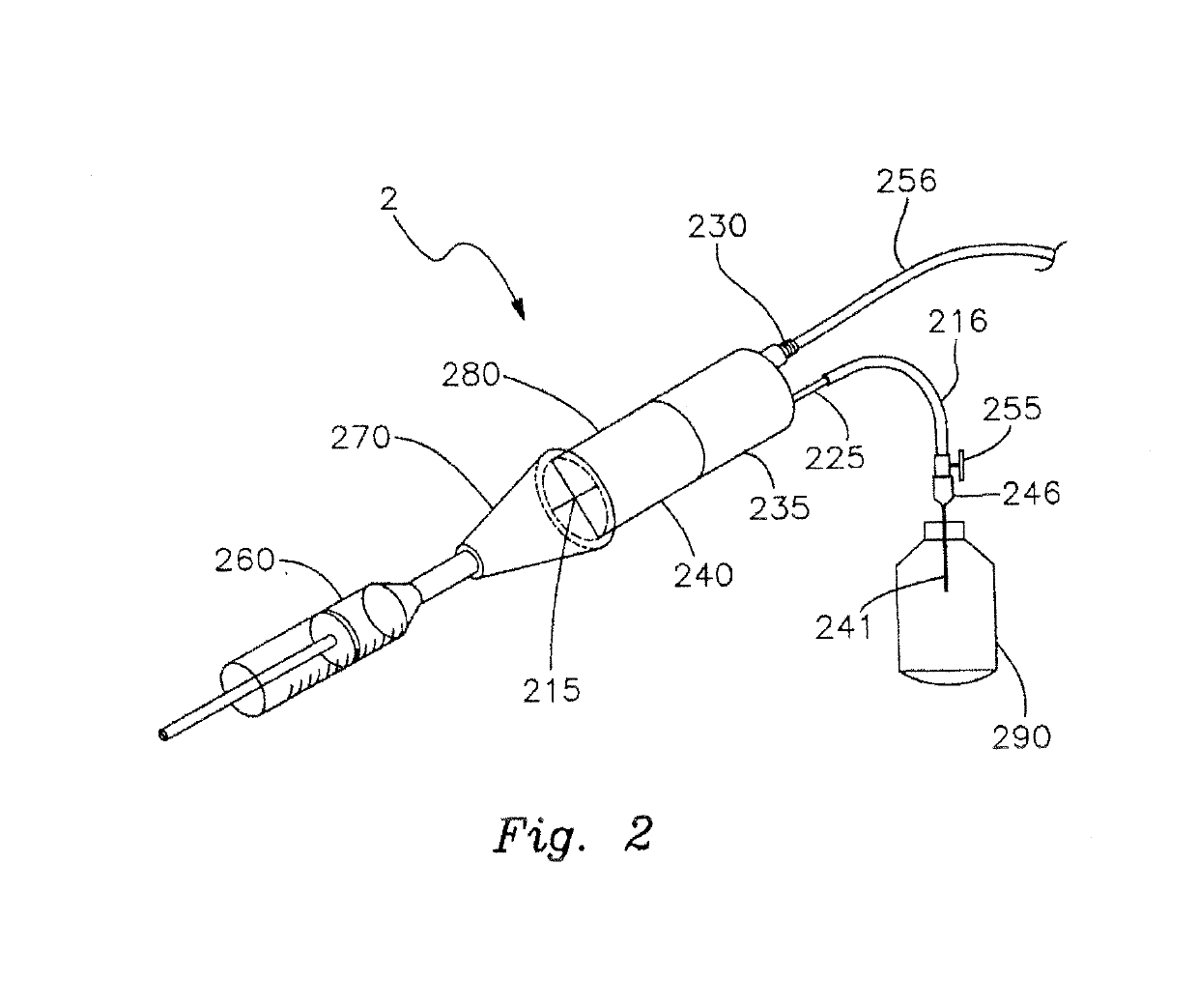
[0021]FIG. 2 is a perspective view of the foam generating tip and medical solution reservoir;

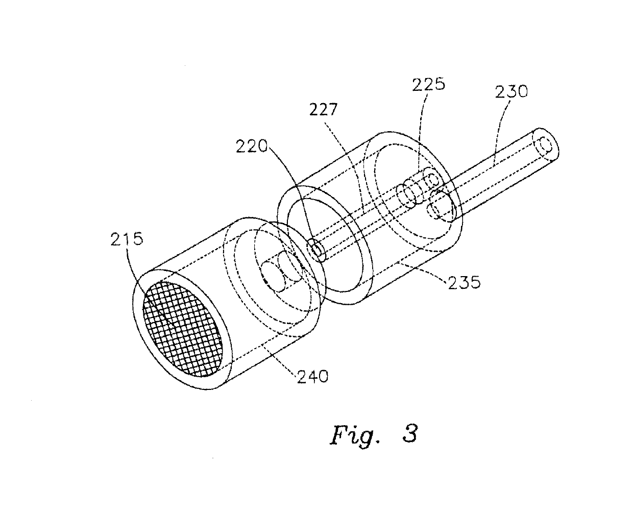
[0022]FIG. 3 is a close-up view of the foam generating tip shown in FIG. 2;

[0023]FIG. 4 is a schematic front view of an alternative compressed gas unit enclosed in a housing;

[0024]FIG. 5 depicts a schematic layout of the components of the compressed gas unit of FIG. 4.

[0025]In FIG. 1 compressed gas unit 1 comprises solenoid 55 with at least one compressed gas (CO2) cylinder 27. In one embodiment, compressed gas cylinder 27 is 25 g or larger. Compressed gas cylinder 27 is secured into position to unit 1 by means of cylinder cartridge puncture valve 26 and a fitting 74. In a preferred emb...


PUM


Abstract

The present invention provides an apparatus for producing medical foam for wound care or hair stimulation. The apparatus includes a foam generation unit having a fluid reservoir, a fluid delivery line and a foam generation tip. The apparatus also includes a compressed gas unit having at least one container of compressed gas, a source of electric power, and a gas regulator valve. A supply of wound care or hair stimulating solution is communicably connected to the foam generation tip such that when the apparatus is operated medical foam is produced by the foam generator tip.

Description

RELATED APPLICATIONS[0001]This application is a continuation of U.S. patent application Ser. No. 15 / 646,623, filed Jul. 11, 2017, which is a continuation of U.S. patent application Ser. No. 14 / 509,459 filed Oct. 8, 2014, which issued as U.S. Pat. No. 9,744,342, which is a continuation of U.S. patent application Ser. No. 13 / 068,680 filed May 17, 2011, which issued as U.S. Pat. No. 8,876,749, which is a continuation in part of U.S. patent application Ser. No. 12 / 652,845 filed Jan. 6, 2010, which is abandoned, which is a continuation-in-part of U.S. patent application Ser. No. 12 / 210,368 filed Sep. 15, 2008, which is abandoned, which is continuation-in-part of U.S. patent application Ser. No. 11 / 945,674 filed Nov. 27, 2007, which issued as U.S. Pat. No. 7,543,760, which claims the benefit of U.S. Provisional Patent Application Ser. No. 60 / 867,323 filed Nov. 27, 2006, the disclosures of which are incorporated herein by reference in their entirety.FIELD OF THE INVENTION[0002]This inventi...

Claims


Application Information

Patent Timeline
IPC IPC(8): A61M35/00A61M37/00A01N25/00
CPCA61B2017/00884A61B2017/00893A61M35/00A01N25/00A61K9/124A61M35/003A61M37/00A61M2202/0225A61M35/30A61H33/14A61H2033/145A61M2205/8225A61K33/00A61M2202/0208A61H2033/143
Inventor LEVY, FRANK
Owner LEVY FRANK
Why Eureka
Try Eureka