Apparatus and process for producing co2 enriched medical foam

a technology of medical foam and apparatus, applied in the direction of aerosol delivery, container discharging methods, spray delivery, etc., can solve the problems of not being put to such use, and achieve the effects of reducing the possibility of malfunction

Pending Publication Date: 2022-02-24
LEVY FRANK
View PDF3 Cites 0 Cited by
  • Summary
  • Abstract
  • Description
  • Claims
  • Application Information

AI Technical Summary

Benefits of technology

[0016]Previous methods utilizing large CO2 tanks and regulators are dangerous because of the risk of a seal, valve, or part malfunction causing a projectile in a medical setting. The present invention is safer as it eliminates this possibility of malfunctio...

Problems solved by technology

The limiting case of the Venturi effect is choked flow, in which a constriction in a pipe or channel limits the total flow rate thro...

Method used


Image

  • Apparatus and process for producing co2 enriched medical foam
  • Apparatus and process for producing co2 enriched medical foam
  • Apparatus and process for producing co2 enriched medical foam

Examples


Embodiment Construction

[0019]Other objects, features and advantages will occur from the following description of a preferred embodiment and the accompanying drawings, in which:

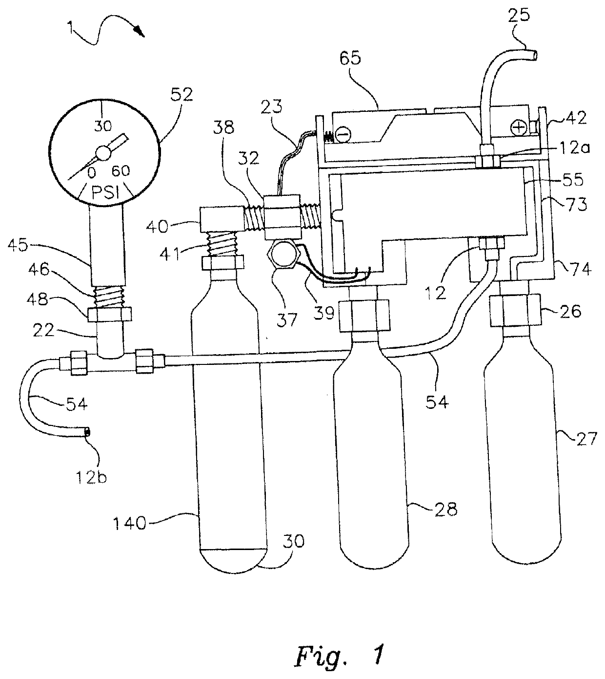
[0020]FIG. 1 is a side perspective and partly schematic view of an apparatus including compressed gas (CO2) cylinders and a solenoid of the present invention;

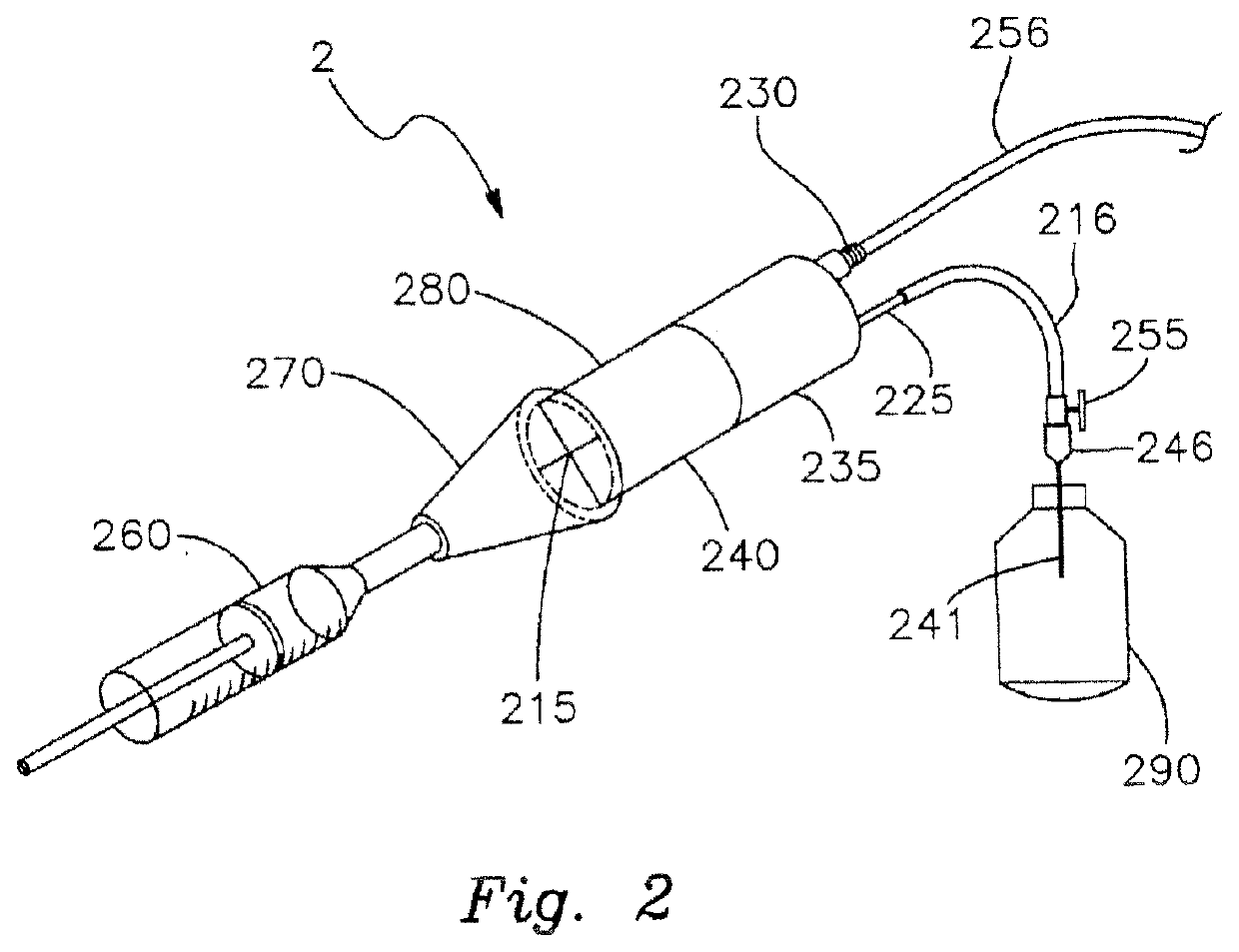
[0021]FIG. 2 is a perspective view of the foam generating tip and medical solution reservoir;

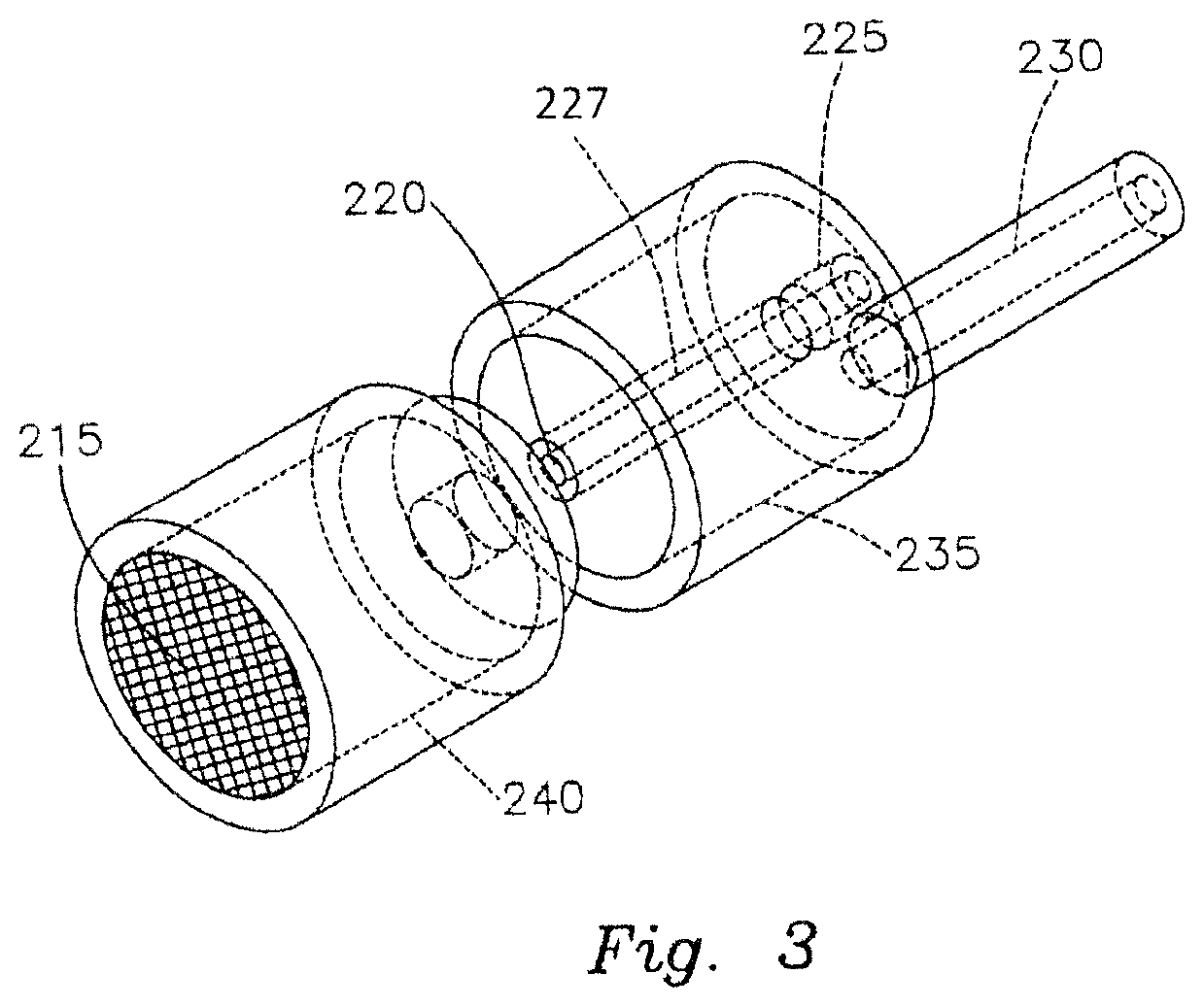
[0022]FIG. 3 is a close-up view of the foam generating tip shown in FIG. 2;

[0023]FIG. 4 is a schematic front view of an alternative compressed gas unit enclosed in a housing;

[0024]FIG. 5 depicts a schematic layout of the components of the compressed gas unit of FIG. 4.

[0025]In FIG. 1 compressed gas unit 1 comprises solenoid 55 with at least one compressed gas (CO2) cylinder 27. In one embodiment, compressed gas cylinder 27 is 25 g or larger. Compressed gas cylinder 27 is secured into position to unit 1 by means of cylinder cartridge puncture valve 26 and a fitting 74. In a preferred emb...


PUM


Abstract

The present invention provides an apparatus for producing medical foam for wound care or hair stimulation. The apparatus includes a foam generation unit having a fluid reservoir, a fluid delivery line and a foam generation tip. The apparatus also includes a compressed gas unit having at least one container of compressed gas, a source of electric power, and a gas regulator valve. A supply of wound care or hair stimulating solution is communicably connected to the foam generation tip such that when the apparatus is operated medical foam is produced by the foam generator tip.

Description

RELATED APPLICATIONS[0001]This application is a continuation of U.S. patent application Ser. No. 16 / 418,434, filed May 21, 2019, which is a continuation of U.S. patent application Ser. No. 15 / 646,623, filed Jul. 11, 2017, which issued as U.S. Pat. No. 10,350,398, which is a continuation of U.S. patent application Ser. No. 14 / 509,459 filed Oct. 8, 2014, which issued as U.S. Pat. No. 9,744,342, which is a continuation of U.S. patent application Ser. No. 13 / 068,680 filed May 17, 2011, which issued as U.S. Pat. No. 8,876,749, which is a continuation in part of U.S. patent application Ser. No. 12 / 652,845 filed Jan. 6, 2010, which is abandoned, which is a continuation-in-part of U.S. patent application Ser. No. 12 / 210,368 filed Sep. 15, 2008, which is abandoned, which is continuation-in-part of U.S. patent application Ser. No. 11 / 945,674 filed Nov. 27, 2007, which issued as U.S. Pat. No. 7,543,760, which claims the benefit of U.S. Provisional Patent Application Ser. No. 60 / 867,323 filed N...

Claims


Application Information

Patent Timeline
IPC IPC(8): A61M35/00A61M37/00A01N25/00
CPCA61M35/003A61M35/00A61K9/124A01N25/00A61M37/00A61K9/0043A61K9/0073F17C7/00F17C2201/0109F17C2201/058F17C2205/0323F17C2205/0326F17C2221/011F17C2221/013F17C2221/014F17C2221/017F17C2221/03F17C2221/031F17C2223/0123F17C2223/0153F17C2223/033F17C2223/035F17C2225/0123F17C2225/033F17C2250/03F17C2250/043F17C2260/04F17C2265/04F17C2270/02A61M35/30A61B2017/00884A61B2017/00893
Inventor LEVY, FRANK
Owner LEVY FRANK
Why Eureka
Try Eureka