Supercharge Your Innovation With Domain-Expert AI Agents!

Differential

a technology of differentials and differential plates, applied in the field of differential plates, can solve the problems of increasing weight, increasing and difficulty in installing the differential on the vehicle, and achieve the effect of restricting the increase in the size of the differential

Inactive Publication Date: 2019-09-26
JTEKT CORP
View PDF0 Cites 0 Cited by
  • Summary
  • Abstract
  • Description
  • Claims
  • Application Information

AI Technical Summary

Benefits of technology

The invention provides a differential that limits the rotation of side gears and includes a spacing member to maintain a gap between driving shafts. This helps to prevent the differential from becoming too large.

Problems solved by technology

Disposing such a spacer in the differential disclosed in JP 2017-161063 A unfortunately increases the axial length of the differential case in accordance with the axial thickness of the spacer, resulting in an increase in the size of the differential.
This may produce adverse effects, such as an increase in weight and difficulty in installing the differential on a vehicle.

Method used


Image

  • Differential
  • Differential
  • Differential

Examples


Embodiment Construction

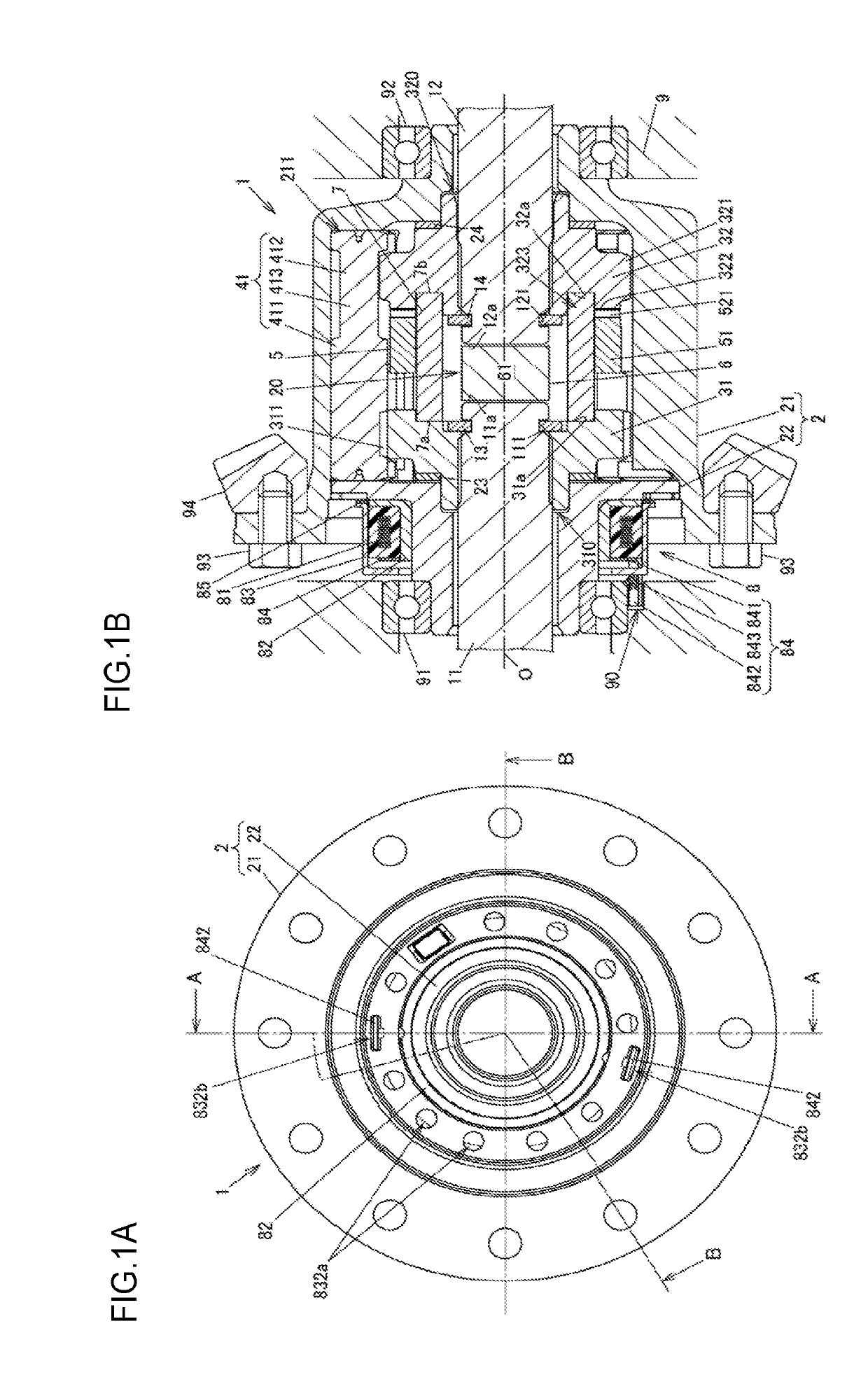
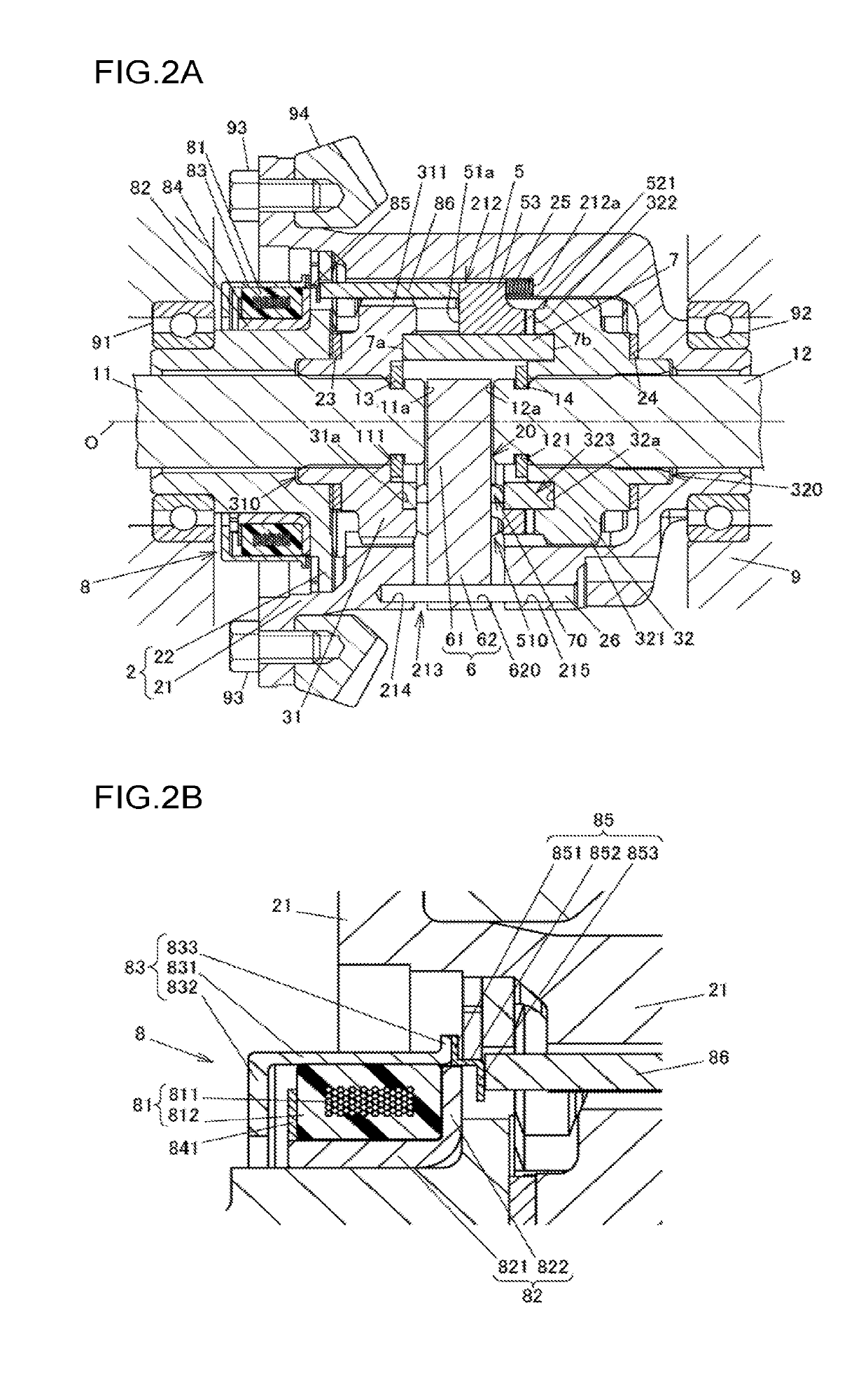
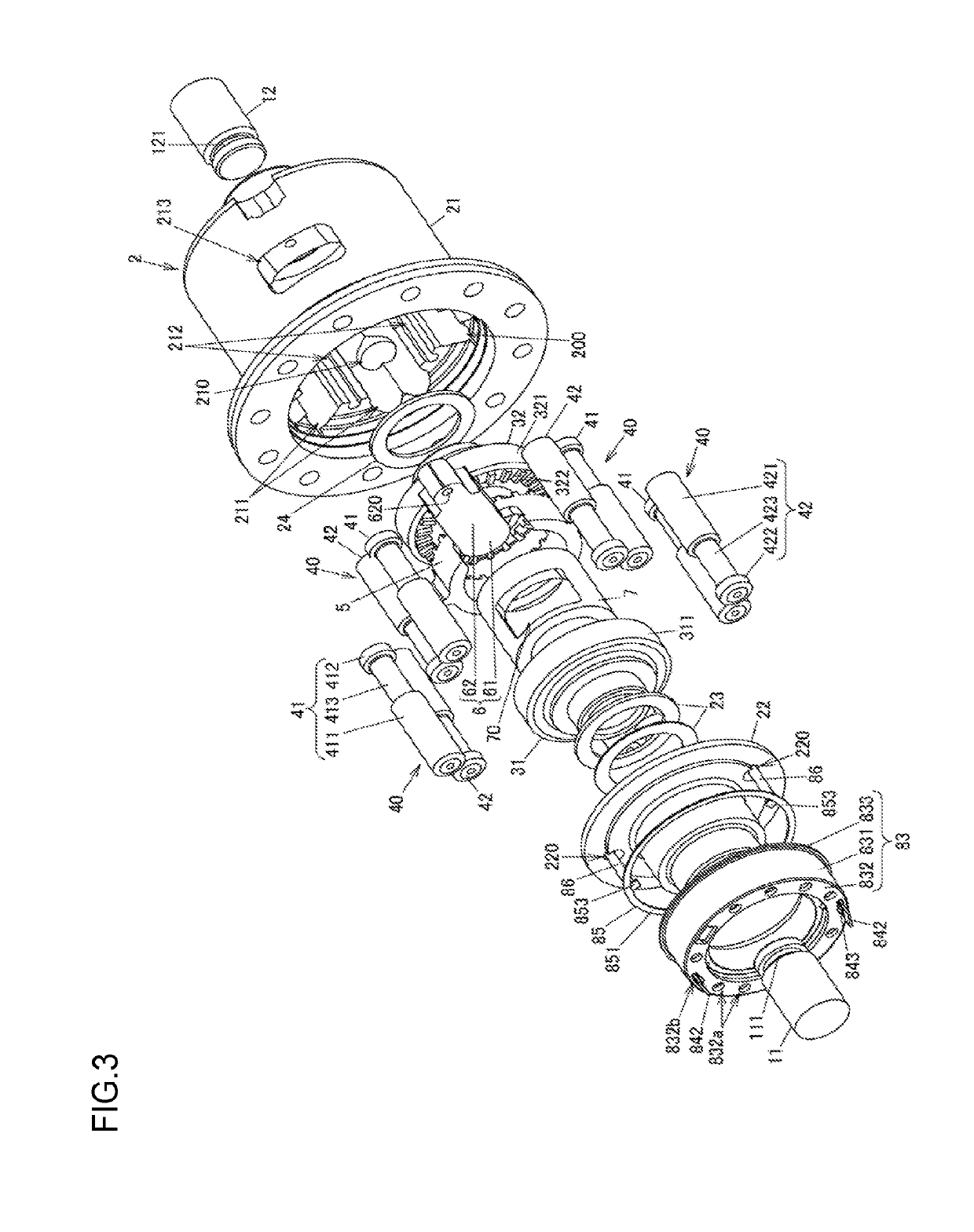
[0025]An embodiment of the invention will be described below with reference to FIGS. 1A to 7C. FIG. 1A is an external view of a differential 1 according to an embodiment of the invention, as viewed in the direction of a rotation axis O of a differential case 2. FIG. 1B is a cross-sectional view of the differential 1 according to the embodiment of the invention, taken along the line A-A in FIG. 1A. FIG. 2A is an overall cross-sectional view of the differential 1 taken along the line B-B in FIG. 1A. FIG. 2B is a partially enlarged cross-sectional view of the differential 1 taken along the line B-B in FIG. 1A. FIG. 3 is an exploded perspective view of the differential 1. FIG. 4 is an exploded perspective view of the differential 1 at an angle different from that of FIG. 3.

[0026]The differential 1 is used as a vehicle differential to distribute a driving force from a driving source (such as an engine or an electric motor) of a vehicle to right and left driving wheels. The differential 1...


PUM


Abstract

A differential includes first and second side gears, a differential case, a spacing member, and a clutch ring. First and second driving shafts are respectively coupled to the first and second side gears. The differential case houses the first and second side gears. The spacing member is inserted into the differential case through an insertion hole of the differential case. A head of the spacing member is disposed in an inter-shaft space between the first and second driving shafts so as to maintain a spacing of a predetermined distance or more between the first and second driving shafts. The clutch ring is axially movably disposed between the first side gear and the second side gear. The clutch ring meshes with the second side gear so as to restrict rotation of the second side gear relative to the differential case.

Description

INCORPORATION BY REFERENCE[0001]The disclosure of Japanese Patent Application No. 2018-053344 filed on Mar. 20, 2018, including the specification, drawings and abstract, is incorporated herein by reference in its entirety.BACKGROUND OF THE INVENTION1. Field of the Invention[0002]The invention relates generally to differentials. More particularly, the invention relates to a differential that is able to differentially distribute a driving force from a driving source to a pair of driving shafts.2. Description of the Related Art[0003]A differential known in the related art may be able to differentially distribute a driving force from a driving source to a pair of driving shafts of a vehicle. Such a differential may have a “differential lock function” to limit differential rotations of the driving shafts. The applicants of the invention disclose a differential of this type in Japanese Patent Application Publication No. 2017-161063 (JP 2017-161063 A).[0004]The differential disclosed in JP...

Claims


Application Information

Patent Timeline
Patent Type & Authority Applications(United States)
IPC IPC(8): F16H48/24F16H48/11F16H48/34F16D27/118F16D11/14
CPCF16H48/34F16H48/24F16H48/11F16D11/14F16H2048/346F16D27/118F16H48/20F16D27/108F16H48/10
Inventor KAMITANI, YASUNORIYOSHISAKA, TADASHIYAMAMORI, MOTOYASU
Owner JTEKT CORP
Features
  • R&D
  • Intellectual Property
  • Life Sciences
  • Materials
  • Tech Scout
  • Unparalleled Data Quality
  • Higher Quality Content
  • 60% Fewer Hallucinations
Learn More