System and method for monitoring an energy consuming appliance

a technology for monitoring systems and appliances, applied in space heating and ventilation control systems, lighting and heating apparatus, heating types, etc., can solve the problems of power consumption costs of appliances, and achieve the effects of reducing customer energy costs, substantial cost savings, and increasing user comfor

Active Publication Date: 2019-09-26
LENNOX IND
View PDF3 Cites 1 Cited by
  • Summary
  • Abstract
  • Description
  • Claims
  • Application Information

AI Technical Summary

Benefits of technology

[0019]In particular embodiments, the instructions further cause the processing circuitry to receive the first measurement associated with the HVAC unit and display the first measurement to a user of the display device.
[0020]Certain embodiments may provide one or more technical advantages. For example, certain embodiments allow an HVAC system to monitor which energy consuming appliances (e.g., an HVAC unit and / or a washing machine) within a building (e.g., an office or residence) are in operation. By monitoring energy consumption per energy consuming appliance, the HVAC system can manage future operation of energy consuming appliances during peak energy periods, which may assist in reducing a customer's energy costs. For instance, the HVAC system may direct cooling to occupied rooms, thus delivering substantial cost savings and increased user comfort.
[0021]As another example, in one or more embodiments, a monitoring device may be installed at the HVAC unit, which mitigates privacy concerns. For instance, the monitoring device may be a stand-alone in-home system under the sole control of a user (e.g., a homeowner) that can provide feedback to the user about energy use without revealing information to an outside party (e.g., a utility company). In certain embodiments, installing the monitoring device at the HVAC unit increases the accuracy of the measurements due to proximity. For instance, installing sensors on the power lines within or near the HVAC unit increases the signal strength generated by the sensors, thereby increasing the accuracy of the energy consuming measurements associated with energy consumption for the HVAC unit.

Problems solved by technology

The second measurement is a cost associated with a power consumption of the appliance.

Method used


Image

  • System and method for monitoring an energy consuming appliance
  • System and method for monitoring an energy consuming appliance
  • System and method for monitoring an energy consuming appliance

Examples


Embodiment Construction

[0032]Embodiments of the present disclosure and its advantages are best understood by referring to FIGS. 1 through 5 of the drawings, like numerals being used for like and corresponding parts of the various drawings.

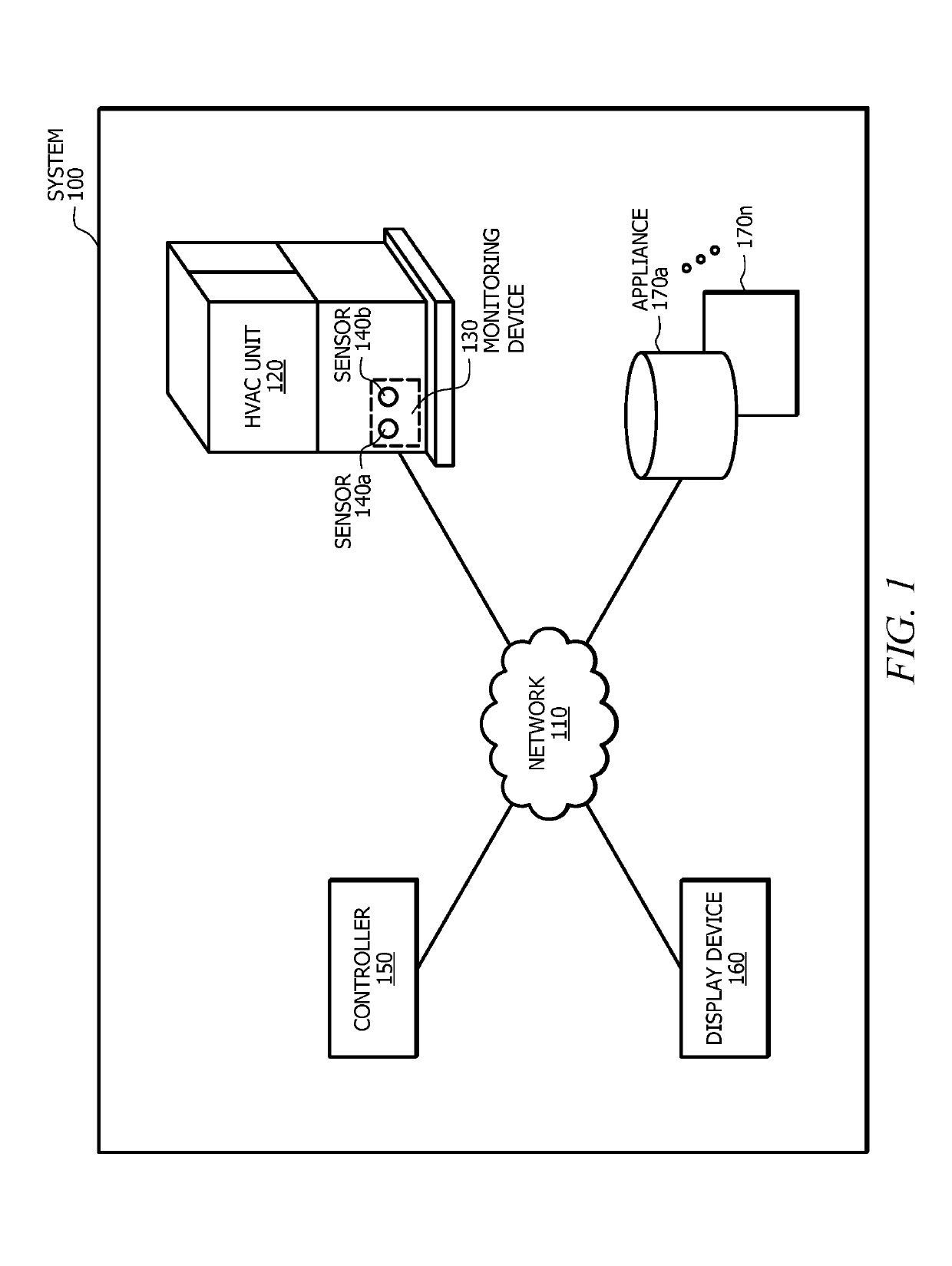
[0033]Buildings (e.g., offices, warehouses, retail, and residences) and other structures often utilize energy consuming appliances to provide an optimal environment. A number of appliances may be placed within a building to provide heating, cooling, lighting, and refrigeration, among other desired functions. For example, a building may include one or more of a heating, ventilation, and air conditioning (HVAC) unit, a water heater, a washing machine, and an oven. Each of these appliances consumes its own unique amount of energy. For example, an HVAC unit may consume more energy during operation than a water heater.

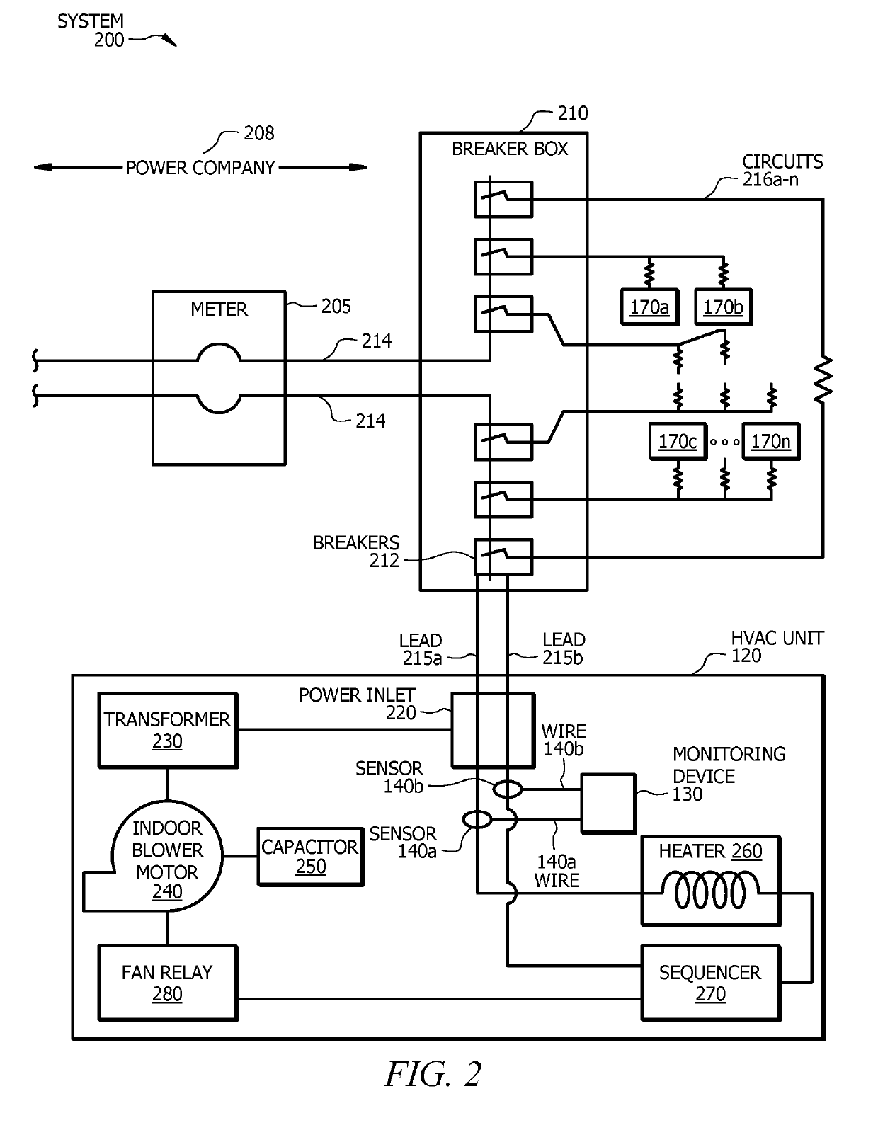
[0034]Certain systems may monitor energy consumption by installing a monitoring device at or near an electrical panel. For example, a monitoring device may be i...


PUM


Abstract

A monitoring system includes a heating, ventilation, and air conditioning (HVAC) unit, one or more sensors coupled to the HVAC unit, and a controller. The one or more sensors are operable to detect one or more properties associated with the HVAC unit. The controller is configured to receive the one or more properties from the one or more sensors and determine a first measurement associated with the HVAC unit based on the one or more properties.

Description

TECHNICAL FIELD[0001]Certain embodiments of this disclosure relate generally to systems and methods for monitoring an energy consuming appliance, and more specifically, using one or more sensors to monitor an energy consuming appliance (e.g., a heating, ventilation, and air conditioning (HVAC) unit).BACKGROUND[0002]A building (e.g., an office or a residence), site, or other space may include one or more energy consuming appliances, such as a heating, ventilation, and air conditioning (HVAC) unit, a water heater, a microwave, an oven, and so on. Energy consuming appliances utilize different amounts of energy at different times. Utility companies may charge customers different rates at different times. For example, a utility company may charge a customer a higher than average rate during periods of high demand (e.g., after normal business hours during a heat wave). Accordingly, customers who operate a large appliance (e.g., an HVAC unit) or several large appliances (e.g., an HVAC unit...

Claims


Application Information

Patent Timeline
Patent Type & Authority Applications(United States)
IPC IPC(8): F24F11/47F24F11/52F24F11/49F24F11/38
CPCF24F11/49F24F11/47F24F11/38F24F11/52
Inventor LAZAR, STEVE
Owner LENNOX IND
Why Eureka
Try Eureka