Method and apparatus for storing and using energy to reduce the end-user cost of energy

a technology of energy storage and end-user cost, applied in the direction of heat storage plants, mechanical power/torque control, ratio control, etc., can solve the problems of less than peak efficiency and performance, heavy burden on utility plants and grids, and inability to meet the needs of users, etc., to reduce the reliance on the power grid, energy costs are relatively low, and energy costs are relatively high

Active Publication Date: 2007-01-02
ENIS BEN M +1
View PDF22 Cites 95 Cited by
  • Summary
  • Abstract
  • Description
  • Claims
  • Application Information

AI Technical Summary

Benefits of technology

[0012]The present invention relates to a method and energy storage system capable of being used by commercial property owners and operators for storing energy during periods when energy costs are relatively low, and then using the stored energy during periods when energy costs are relatively high, to reduce reliance on the power grid during the high demand periods, and therefore, reduce the operating costs associated therewith, and to do so in a manner that helps obtain a cost savings over an extended period of time.
[0013]The present invention is preferably to be used by commercial property owners and operators, such as office buildings, shopping centers, and other end-users of energy, and in this respect, the present system differs from past systems, insofar as it is not intended to be used by and in connection with energy suppliers, such as large utility and power supply plants and grids. That is, the present system preferably relates to the manner in which an “end-user” of energy can implement energy and costs savings, by using energy storage and time-shifting methods, to control and regulate the consumption of energy in a manner that achieves a cost savings over an extended period of time. This cost saving method is referred to as “Time-Of-Use” or TOU.
[0014]In this respect, one aspect of the present method and system preferably relates to being able to accurately forecast and predict the energy demands and peaks that might occur on a daily basis, by recording and analyzing the prior day's history, as well as the overall energy demand histories, using short and long term forecasts, and then setting up a variable energy storage / use plan or schedule that helps to reduce the peak demands by time-shifting the energy that is used, i.e., reducing consumption during high demand / high cost periods, by using the energy stored during low demand / low cost periods during the high demand / high cost periods.

Problems solved by technology

And, because most businesses and commercial properties are required to operate during the day, they typically need substantial electrical energy during the daytime hours to provide power for utilities, including lighting, heating, cooling, etc.
These peak demands can place a; heavy burden on utility plants and grids that supply electrical power to commercial properties.
Utility plants and grids often have to be constructed to meet the highest demand periods, which means that during the low demand periods, they will inevitably operate inefficiently, i.e., at less than peak efficiency and performance.
Failure to properly account for such high demand periods, such as by over-designing the facilities to meet the peak demands, can result in the occurrence of frequent power outages and failures.
Also, a failure in one area of the grid can cause tremendous stress and strain in other areas, wherein the entire system can fail, i.e., an entire regional blackout can occur.
These demands can also place expensive burdens on commercial property owners and operators.
And because most commercial property owners are forced to operate during the day, they are most often forced to pay the highest energy costs during the highest demand periods.
Nevertheless, since most commercial property owners and operators must operate their businesses during the day, and alternative sources of energy are not always readily available, they often find themselves having to use energy during the highest rate periods.
Moreover, because energy consumption rates can fluctuate, and surges and spikes can occur at various times, potentially huge demand charges may be applied.
Thus far, however, one of the main disadvantages of such systems is that they are relatively energy inefficient.
For example, compressed air energy systems have a tendency to lose a significant portion of the energy that is stored, so that the energy used from storage ends up actually costing more than the energy that was stored.
Even though there are some advantages to such energy storage systems, the added costs associated with installing and operating such systems can become a financial burden, especially at the end-user level.
Accordingly, commercial property owners and operators that use energy often have difficulty justifying the cost of installing and using such systems.
Moreover, because of the expense of installation, they may have difficulties obtaining financing and approval, e.g., to attract investors and / or lenders to spend the money needed to develop and install such a system, because they often doubt whether they will be able to recoup the costs.

Method used


Image

  • Method and apparatus for storing and using energy to reduce the end-user cost of energy
  • Method and apparatus for storing and using energy to reduce the end-user cost of energy
  • Method and apparatus for storing and using energy to reduce the end-user cost of energy

Examples


Embodiment Construction

[0017]This discussion will begin by discussing some of the basic components of the energy storage system apparatus that can be used by the present invention. The invention contemplates that various energy storage systems can be used in connection with the methods discussed herein. Nevertheless, the following discussion describes a preferred system that can be used in connection with the present invention.

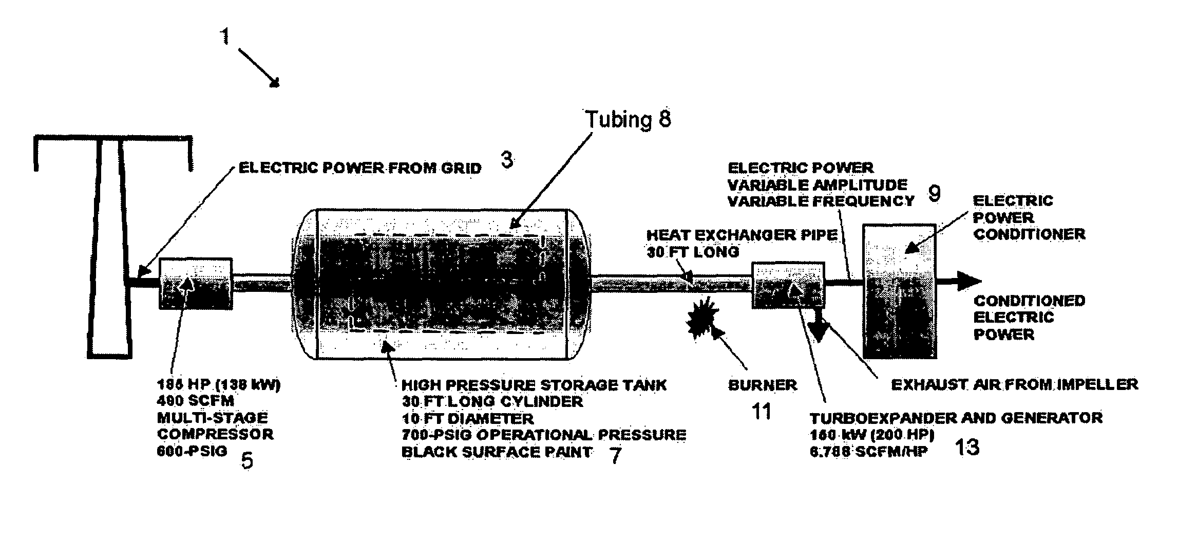
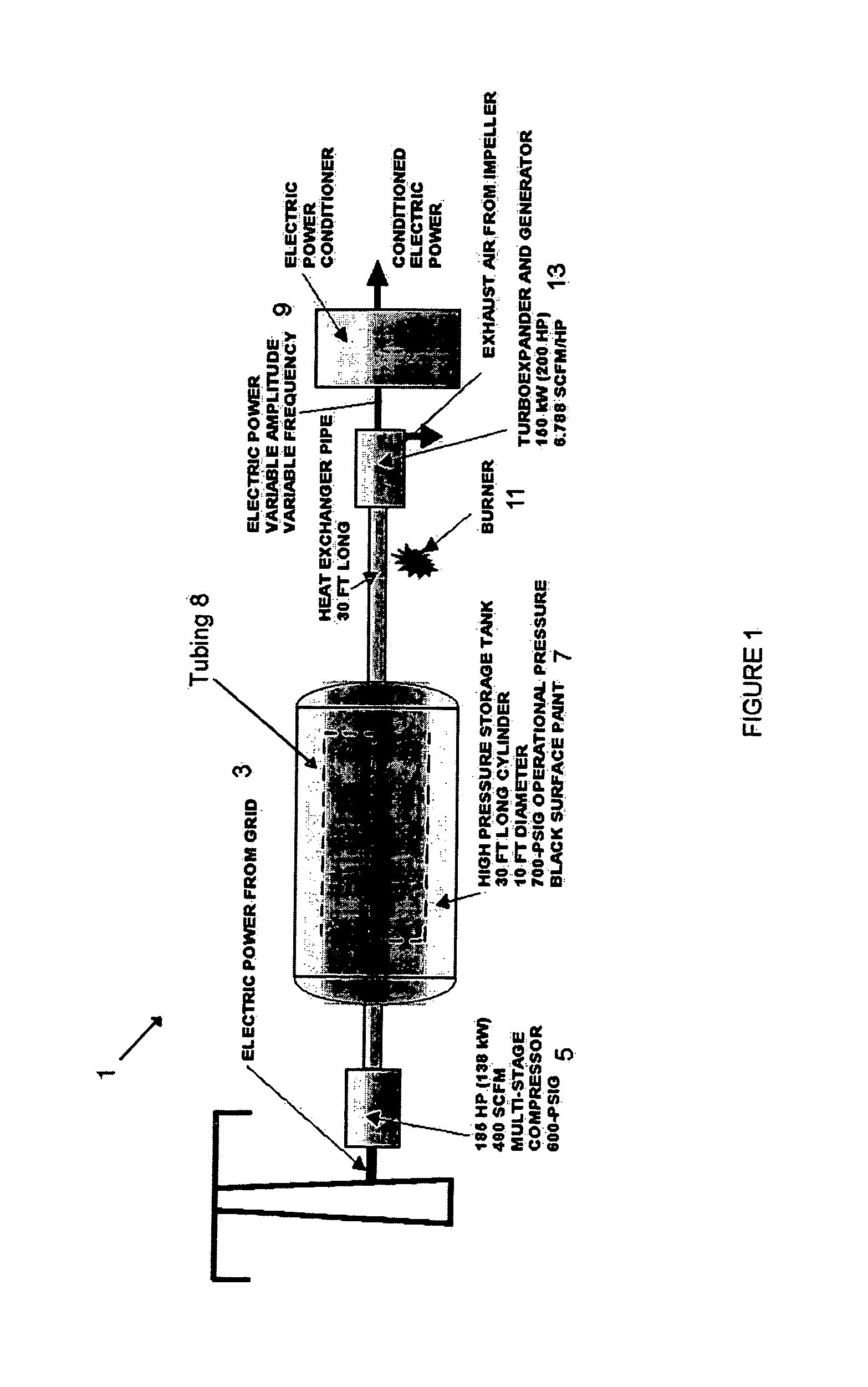
[0018]The system generally comprises a compressed air energy storage system small enough to be housed within a commercial property, whether an office building, shopping center, or other end-user of energy. For example, the system can be installed in a basement of an office building, shopping center or commercial complex, where other utility equipment might be located. The storage tank can also be located on the roof or other outdoor location, and, for example, painted black, to enable the tank to absorb heat energy from the sun, as will be discussed.

[0019]As shown in FIG. 1, the sys...


PUM


Abstract

The invention relates to an energy storing method and apparatus for use by end-users of energy, such as commercial property owners and operators. The system differs from past systems, insofar as it is not intended to be used by and in connection with energy suppliers, such as large utility and power supply plants and grids. The system preferably relates to the manner in which an end-user of energy can implement energy and costs savings, by using energy storage and time-shifting methods, to control and regulate the consumption of energy in a manner that achieves a cost savings over a period of time. One aspect of the method relates to accurately forecasting and predicting the energy demands and peaks that might occur on a daily basis, by recording and analyzing the prior day's history, as well as the overall energy demand histories, using short and long term forecasts, and then setting up a variable energy storage / use plan or schedule that helps to reduce the peak demands by time-shifting the energy that is used, i.e., reducing consumption during high demand / high cost periods, and using the energy stored during low demand / low cost periods during the high demand / high cost periods.

Description

RELATED APPLICATION[0001]This application claims the benefit of the filing date of U.S. Provisional Application Ser. No. 60 / 514,801, entitled “Method And Apparatus For Storing And Using Energy”, filed on Oct. 27, 2003.FIELD OF THE INVENTION[0002]The present invention relates to the field of energy storage systems.BACKGROUND OF THE INVENTION[0003]There are literally hundreds of thousands of office buildings and other commercial property located in the United States and throughout the world (hereinafter “commercial properties”). And, because most businesses and commercial properties are required to operate during the day, they typically need substantial electrical energy during the daytime hours to provide power for utilities, including lighting, heating, cooling, etc. This is particularly true with heating and cooling requirements, such as during the extreme winter and extreme summer months, wherein the energy needed to maintain a comfortable work environment can be relatively high.[...

Claims


Application Information

Patent Timeline
Patent Type & Authority Patents(United States)
IPC IPC(8): G05D11/00B60K16/00F02C6/00F02C6/16F03D9/00F03D9/02F03G6/00F25D3/00G06F19/00H02P9/00
CPCF28D20/00G06Q10/00G06Q50/06H02J15/006H02J3/28F24D2200/16F24J2/34Y02T10/84Y02E10/46Y02E60/142Y02E60/15F24S60/30Y02E60/14H02J3/003H02J2310/64H02J2203/10Y04S20/222Y04S20/244Y02B70/30Y02B70/3225G06Q10/04Y02E60/16
Inventor ENIS, BEN M.LIEBERMAN, PAUL
Owner ENIS BEN M
Why Eureka
Try Eureka