Supercharge Your Innovation With Domain-Expert AI Agents!

Hybrid depth detection and movement detection

a technology of depth detection and movement detection, applied in the direction of image enhancement, instruments, and using reradiation, can solve the problems of user into a mixed-reality environment, many challenges, difficulties, and costs, and conventional depth detection systems fail to adequately determine the depth of a smooth surface, and conventional head tracking systems fail to adequately track the movements of a hmd

Active Publication Date: 2019-09-26
MICROSOFT TECH LICENSING LLC
View PDF2 Cites 8 Cited by
  • Summary
  • Abstract
  • Description
  • Claims
  • Application Information

AI Technical Summary

Benefits of technology

This patent describes a method and system for using head-mounted devices (HMDs) with a stereo camera system and an IR dot-pattern illumination to detect depth and movement. The cameras on the HMDs have fields of view that overlap, and the HMDs also have one or more IR dot-pattern illuminators and one or more flood IR light illuminators. The depth detection and movement tracking are achieved by analyzing the images obtained from the cameras and the IR dot-pattern illumination. The technical effect of this invention is to provide a more precise and realistic way of perceiving the surrounding environment in a novel and immersive way through the use of HMDs and stereo cameras.

Problems solved by technology

However, the process of immersing a user into a mixed-reality environment creates many challenges, difficulties, and costs, particularly with regard to determining depth and tracking movement.
For instance, by way of example, conventional depth detection systems fail to adequately determine the depth of a smooth surface (e.g., a wall) in a mixed-reality environment because those systems fail to adequately distinguish one part of the smooth surface from another part.
Furthermore, conventional head tracking systems fail to adequately track the movements of a HMD in a low light environment because those systems fail to adequately identify a sufficient number of anchor points.
This additional hardware adds to the overall cost, weight, battery consumption and size of the HMD systems.

Method used


Image

  • Hybrid depth detection and movement detection
  • Hybrid depth detection and movement detection
  • Hybrid depth detection and movement detection

Examples


Embodiment Construction

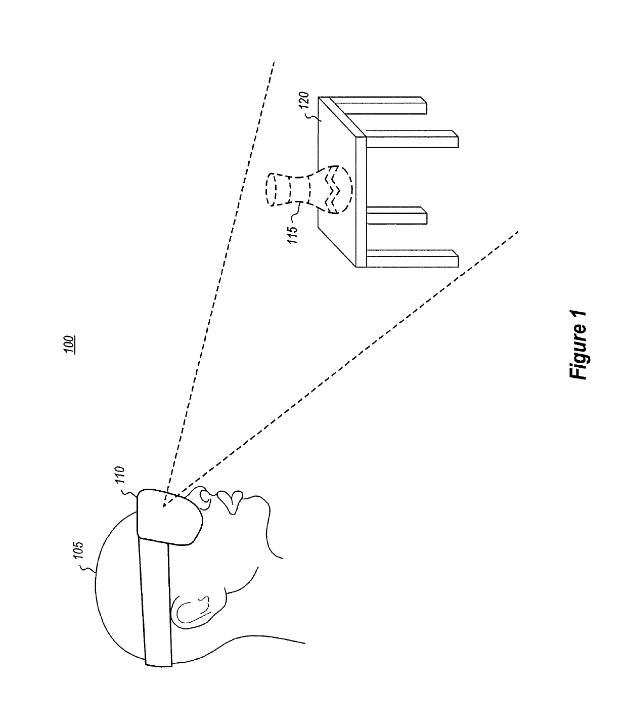
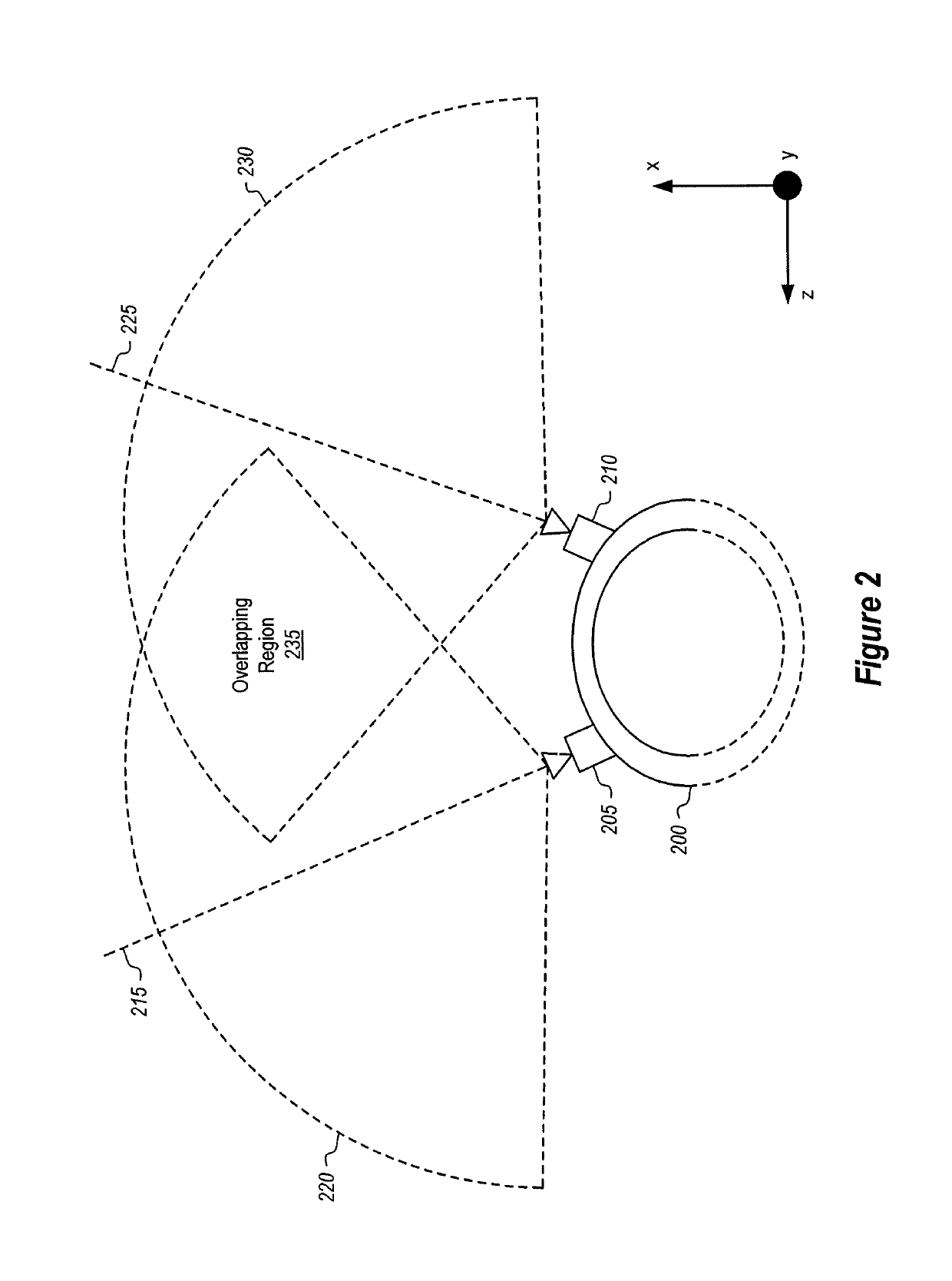
[0034]At least some of the embodiments described herein relate to head-mounted devices (HMD) configured to perform depth detection and movement detection. The HMD may include a stereo camera pair comprising a first and second camera which are both mounted on the HMD and which are both able to detect visible light and infrared (IR) light. Such positioning is beneficial for motion tracking purposes because it allows the cameras to capture a large amount of area in the surrounding environment. By capturing more area, the HMD is better able to track movements. Furthermore, at least a part of the cameras' fields of view overlap with one another.

[0035]The HMD also includes one (or more) IR dot-pattern illuminators. The IR dot-pattern illuminator emits an IR dot-pattern illumination that spans an illumination area. The HMD uses the IR dot-pattern illumination to determine depth for at least a part of the environment. The HMD also includes one or more flood IR light illuminators that emit a...


PUM


Abstract

A head-mounted device (HMD) is configured to perform depth detection in conjunction with movement tracking. The HMD includes a stereo camera pair comprising a first camera and a second camera, both of which are mounted on the HMD. The fields of view for both of the cameras overlap to form an overlapping field of view. These cameras are configured to detect both visible light and infrared (IR) light. The HMD also includes an IR dot-pattern illuminator that is configured to emit an IR dot-pattern illumination. The HMD uses the IR dot-pattern illumination to determine an object's depth. The HMD also includes one or more flood IR light illuminators that emit a flood of IR light. The HMD uses the flood of IR light to track at least its own movements, and sometimes even hand movements, in various environments, even low light environments.

Description

BACKGROUND[0001]Mixed-reality systems, including virtual-reality and augmented-reality systems, have received significant attention because of their ability to create truly unique experiences for their users. For reference, conventional virtual-reality (VR) systems create a completely immersive experience by restricting their users' view to only a virtual environment. This is often achieved through the use of a head-mounted device (HMD) that completely blocks any view of the real world. As a result, a user is entirely immersed within the virtual environment. In contrast, conventional augmented-reality (AR) systems create an augmented-reality experience by visually presenting virtual objects that at least partially occlude portions of the real world.[0002]As used herein, VR and AR systems are described and referenced interchangeably. Unless stated otherwise, the descriptions herein apply equally to all types of mixed-reality systems, which (as detailed above) includes AR systems, VR ...

Claims


Application Information

Patent Timeline
IPC IPC(8): G06T7/529G01S17/89G01S17/66G01B11/25H04N13/239H04N13/254H04N13/344H04N13/366
CPCH04N13/254H04N13/344G06T2207/10028G01S17/66G06T7/529G01S17/89G06T2207/30196G06T7/73G06T7/62H04N13/366G01B11/2545G01B11/24G02B27/017H04N13/332G06T7/586H04N13/239
Inventor PRICE, RAYMOND KIRKBLEYER, MICHAELREIDY, CHRISTOPHER FRANCIS
Owner MICROSOFT TECH LICENSING LLC
Features
  • R&D
  • Intellectual Property
  • Life Sciences
  • Materials
  • Tech Scout
  • Unparalleled Data Quality
  • Higher Quality Content
  • 60% Fewer Hallucinations
Learn More