
Liquid Piston Stirling Engine with Linear Generator

a technology of liquid piston and stirling engine, which is applied in the direction of stirling engines, machines/engines, stirling type engines, etc., can solve the problems of friction and wear of common stirling engines, and the sealing of moving parts is subject to degradation

Active Publication Date: 2019-10-24
STRATUM VENTURES LLC
View PDF0 Cites 0 Cited by
  • Summary
  • Abstract
  • Description
  • Claims
  • Application Information

AI Technical Summary

Benefits of technology

The invention is a liquid piston Stirling engine linear generator device that uses a Stirling engine to generate electrical current. The device includes a U-shaped chamber with two vertical segments and a horizontal segment, a liquid piston with a non-compressible liquid, a cycle head with heat exchangers, a gas spring chamber, and a slider and stator with wire coils. The device generates electrical current through the movement of the slider and stator. The technical effects of the invention include improved efficiency and reduced noise in the generation of electrical current.

Problems solved by technology

Common Stirling engines suffer from problems relating to friction and wear, as moving seals are subject to degradation and failure over time.

Method used


Image

  • Liquid Piston Stirling Engine with Linear Generator
  • Liquid Piston Stirling Engine with Linear Generator

Examples


Embodiment Construction

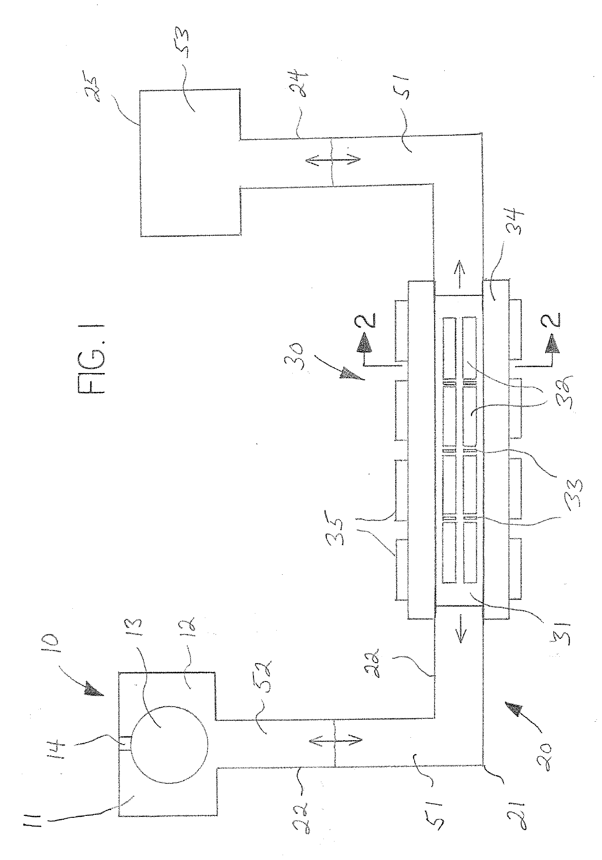
[0011]In various embodiments the invention comprises in general a liquid piston Stirling engine electrical generator, the generator being a linearly reciprocating electrical generator that is powered by a Stirling engine having a liquid, referred to as a liquid piston, that is displaced by the cyclic expansion and contraction / compression in volume of a gas, such as air, as illustrated in FIG. 1.

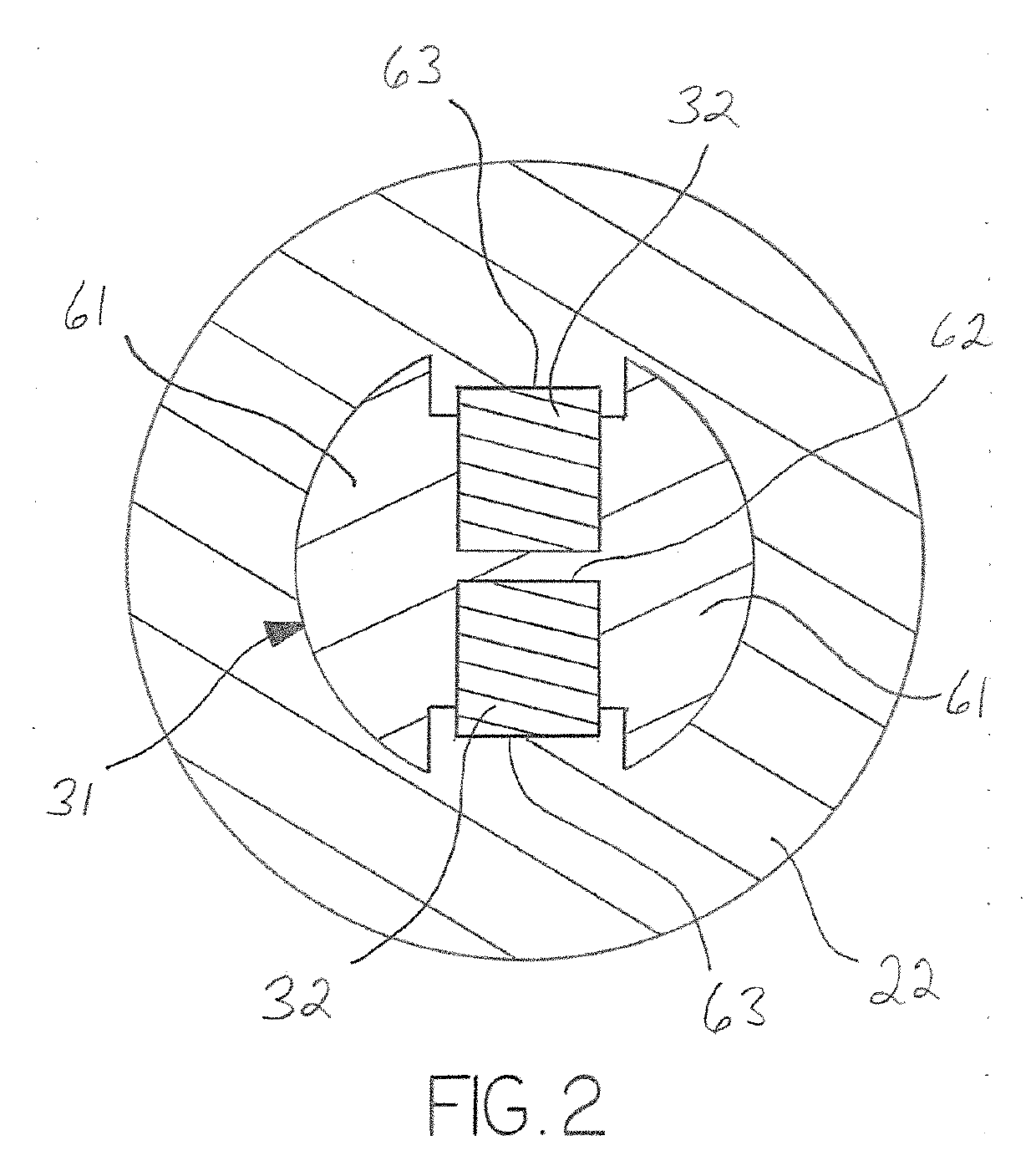
[0012]The liquid piston 51 and dynamic components of the linear generator 30 are retained within a liquid piston assembly 20 comprising a U-shaped tube or chamber 21, the chamber 21 being oriented in use to consist of a two upwardly extending, first and second vertical segments 23 and 24 connected to a linear horizontal segment 22, the combination providing a continuous opening to receive a quantity of an essentially non-compressible liquid, such as water, oil or hydraulic fluid, which defines the liquid piston 51 and which is present in sufficient quantity to fill the horizontal segment 22 a...


PUM


Abstract

A liquid piston Stirling engine electrical generator, the generator being a linearly reciprocating electrical generator that is powered by a Stirling engine having a liquid piston that is displaced by the cyclic contraction and expansion of a gas resulting from increases and decreases in temperature. The liquid piston and dynamic components of the linear generator are retained within a U-shaped tube or chamber, the tube being oriented in use to consist of a two upwardly extending, first and second vertical segments joining a horizontal segment. A liquid, such as oil or hydraulic fluid, is present in sufficient quantity to fill the horizontal segment and extend upward into the vertical segments.

Description

BACKGROUND OF THE INVENTION[0001]This application relates generally to the field of electrical power generation and more particularly to electrical generation by Stirling engines. Even more particularly, the application relates to Stirling engines driving a liquid piston and electrical generation by reciprocal linear motion of magnets within a static coil.[0002]Stirling engines in various embodiments are well known and can be generally described in their most common form as a heat engine that operates by cyclic expansion and contraction of a gas, often referred as the working fluid, at different temperatures. A Stirling engine is a thermo-dynamic, closed-cycle, regenerative heat engine wherein the gaseous working fluid is permanently retained within the system. An internal heat exchanger and thermal store, known as a regenerator, differentiates the Stirling engine from other closed cycle hot air engines.[0003]Common Stirling engines suffer from problems relating to friction and wear...

Claims


Application Information

Patent Timeline
Patent Type & Authority Applications(United States)
IPC IPC(8): F02G1/053
CPCF02G2270/30F02G1/053F02G2243/36F02G2270/70F02G2280/10
Inventor GOYETTE, DONALD
Owner STRATUM VENTURES LLC
Learn More