

Memory validity states in time-travel debugging
- Summary
- Abstract
- Description
- Claims
- Application Information
AI Technical Summary
Benefits of technology
Problems solved by technology
Method used
Image


Examples
Embodiment Construction
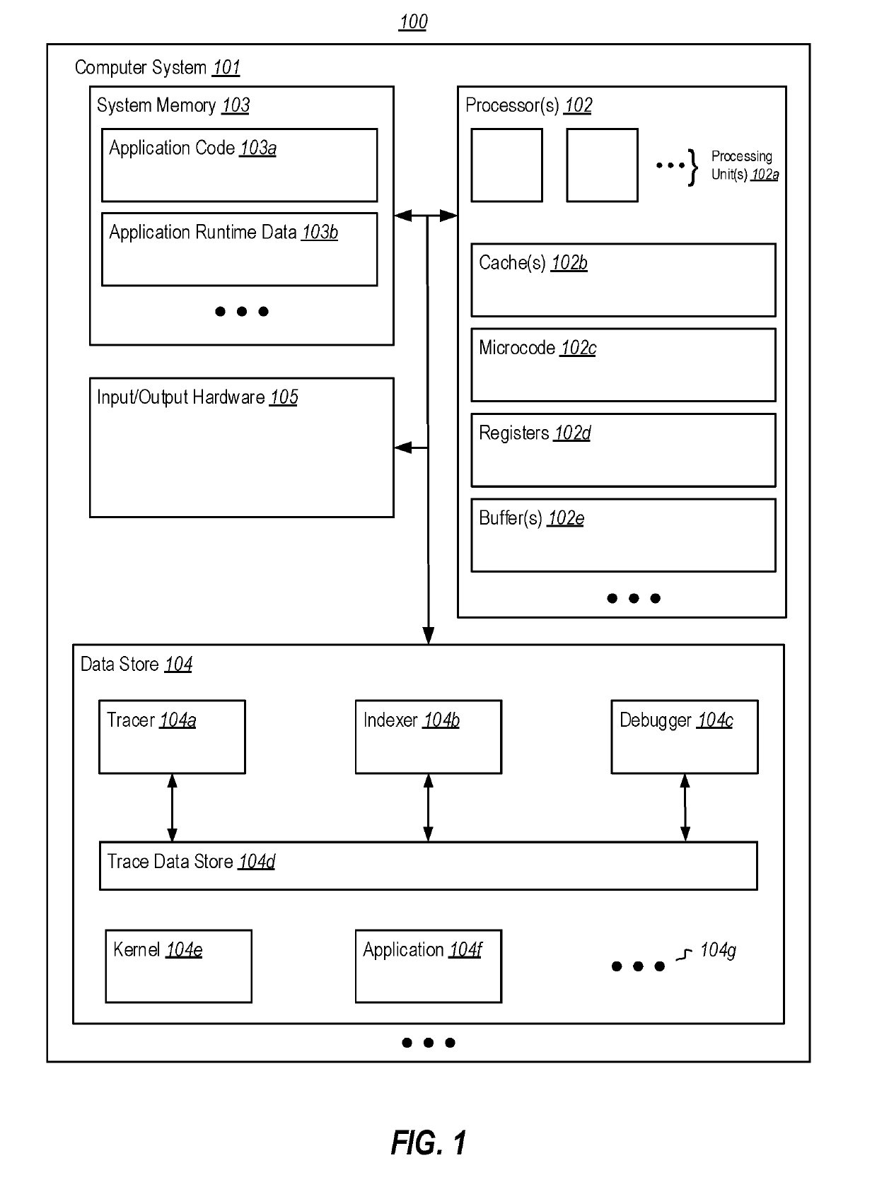
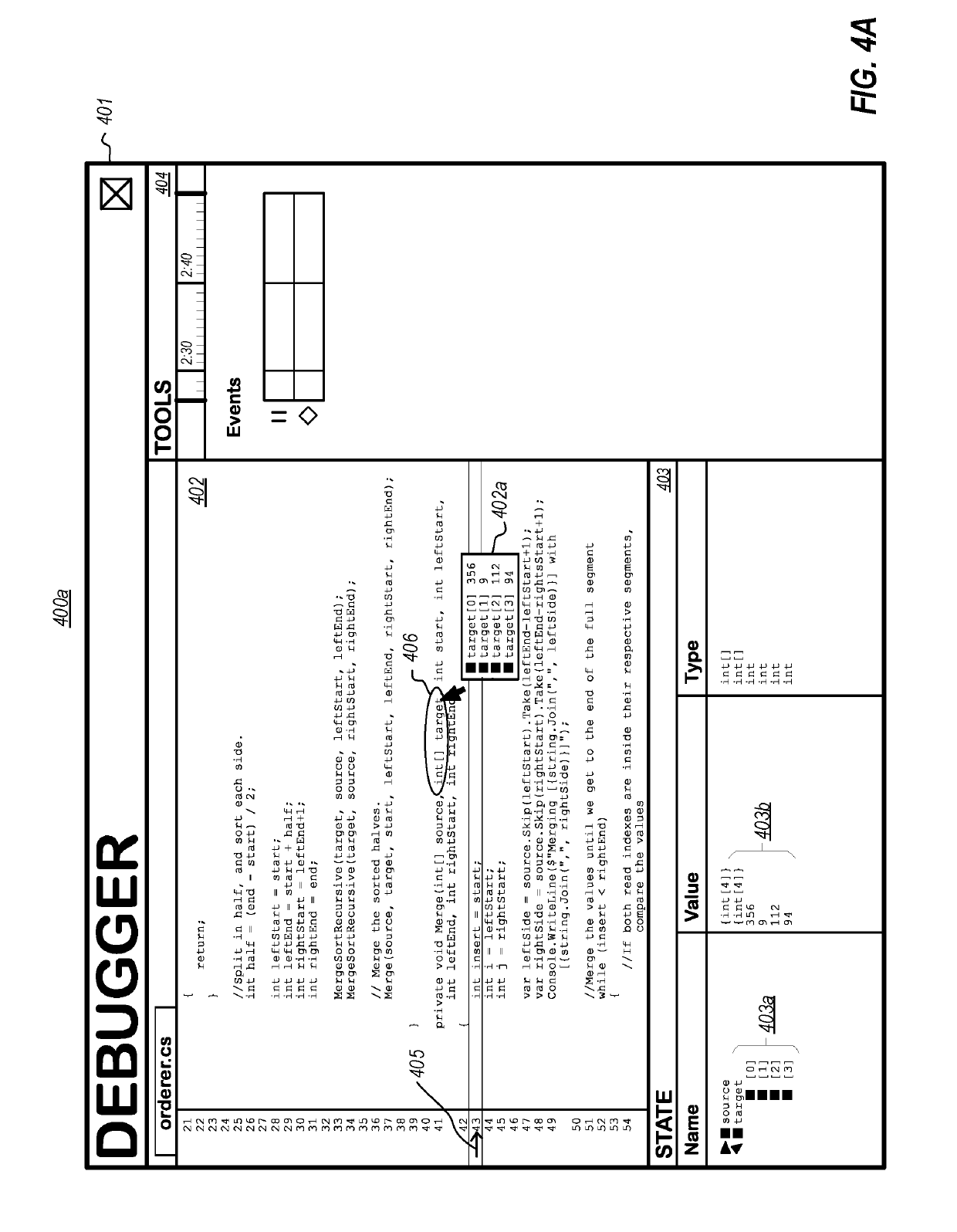
[0033]At least some embodiments described herein leverage the wealth of information recorded in bit-accurate time travel traces to provide rich debugging experiences, including providing one or more visualizations of historical state associated with code element(s) that are part of a prior execution of an entity. For example, embodiments of a debugger could leverage time travel trace data, including data indicative of both when a memory value was read from a cache, as well as how long the value remained present in the cache, to present in a debugger known data values of one or more variables and / or data structures, to present in a debugger return value(s) of one or more functions (including functions that rely on a plurality of memory values), etc. Visualizations of such data could include indicating whether a value of a code element is known, unknown, previously known, known in the future, known with an indicated certainty, and the like, with respect to a current execution time poi...
PUM
 Abstract
Description
Claims
Application Information