
Virtual reality based visual field testing system

a virtual reality and testing system technology, applied in the field of visual field testing systems, can solve the problems of invalid testing, long patient hold still time, and no way to test the visual field on a bedbound patien

Inactive Publication Date: 2019-11-21
LEWIS TRACEY LYNNE
View PDF0 Cites 0 Cited by
  • Summary
  • Abstract
  • Description
  • Claims
  • Application Information

AI Technical Summary

Benefits of technology

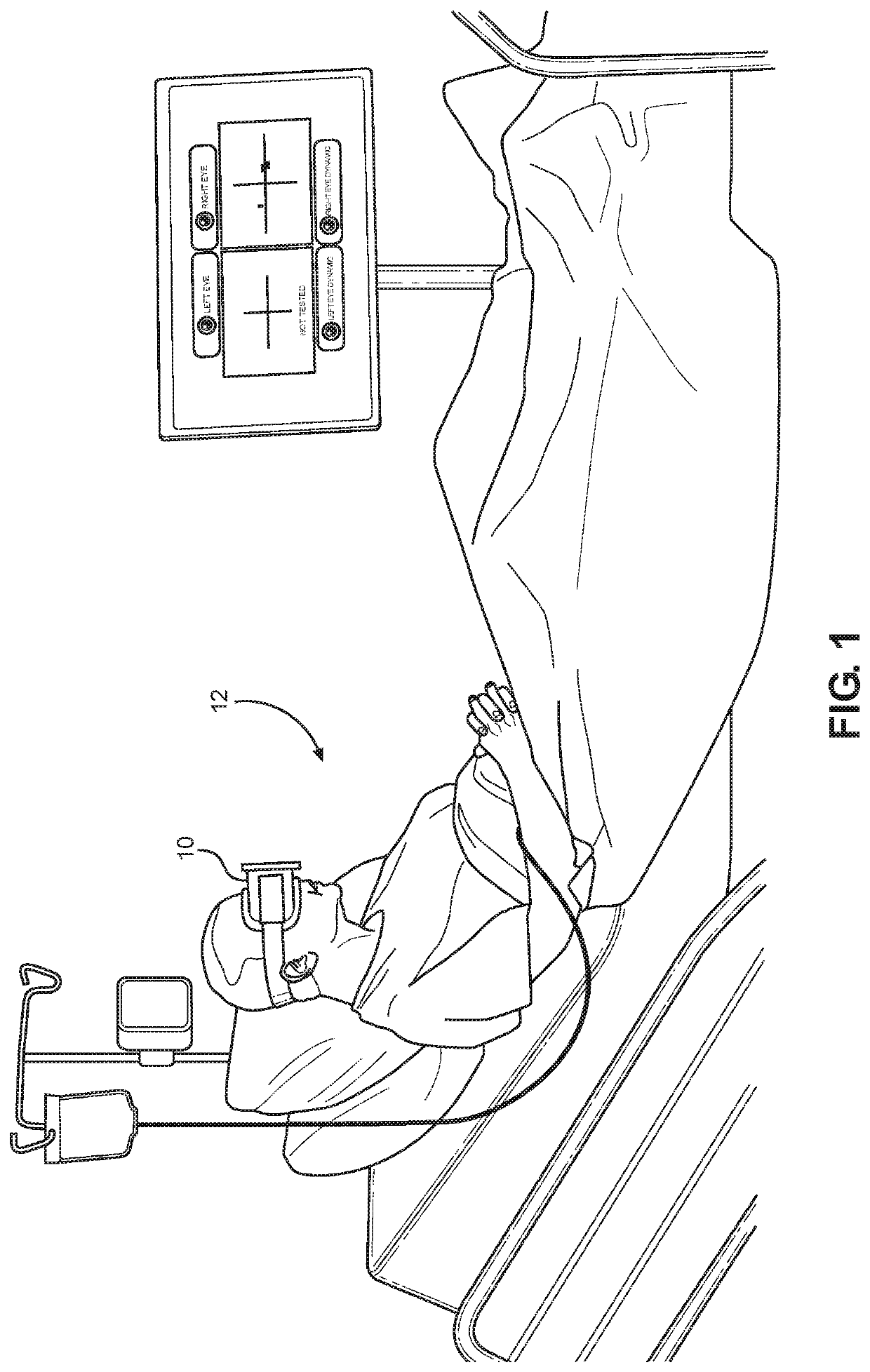
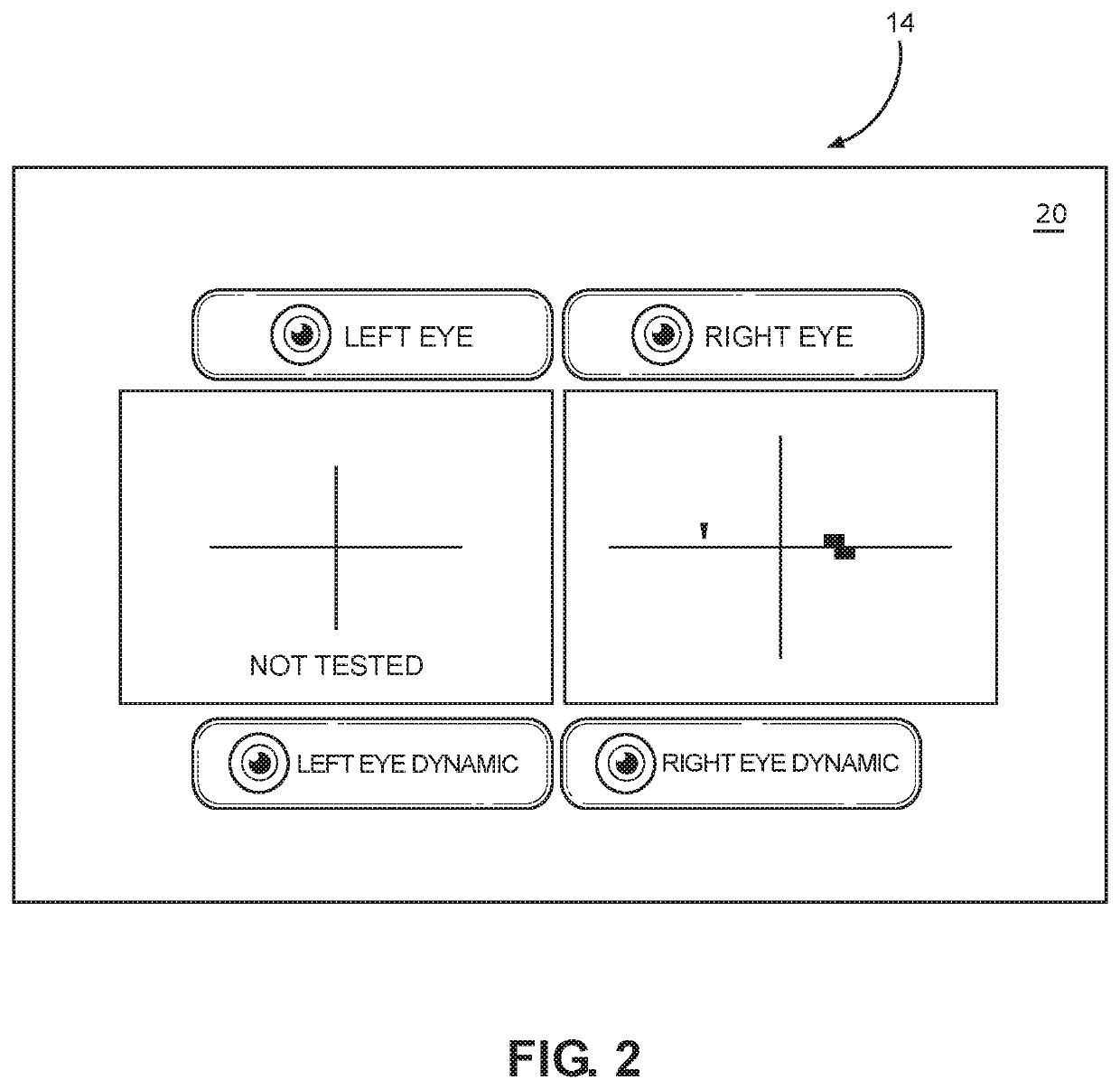
This present invention provides a method to test the visual field of a person using a virtual reality device. The virtual reality device is worn over the eyes of the person and includes a central fixation standard / static automated perimetry testing system. This testing involves showing discrete targets on the virtual reality device at different positions and intensities, and the person's eyes are tested for their ability to fix on these targets. The virtual reality device helps to maintain a constant distance between the person's eye and the device's user interface, making the testing more accurate. This invention provides a convenient and efficient way to test a person's visual field.

Problems solved by technology

Similarly, if the patient looks away, the test is invalid.
Each eye takes over twenty minutes, which is a long time for patients to hold still.
As a result, there is no way to test the visual field on a bed bound patient, for example in a nursing home or an elderly, disabled patient.
In the emergency room, however, it can take about 24 hours to diagnose a stroke because the anoxia—i.e., the swelling and subsequent death of brain cells—may not show up on MRI or CT scan for approximately one day.
During this time period, TPA is not used because the diagnosis is not a certainty, and thus risk may not out way benefit—to the detriment of the patient suffering from an undiagnosed stroke.
However, because a patient suffering from a stroke may not be able to properly perform a visual field test (because of the aforementioned requirements) they may go untreated.

Method used


Image

  • Virtual reality based visual field testing system
  • Virtual reality based visual field testing system
  • Virtual reality based visual field testing system

Examples


Embodiment Construction

[0014]The following detailed description is of the best currently contemplated modes of carrying out exemplary embodiments of the invention. The description is not to be taken in a limiting sense, but is made merely for the purpose of illustrating the general principles of the invention, since the scope of the invention is best defined by the appended claims.

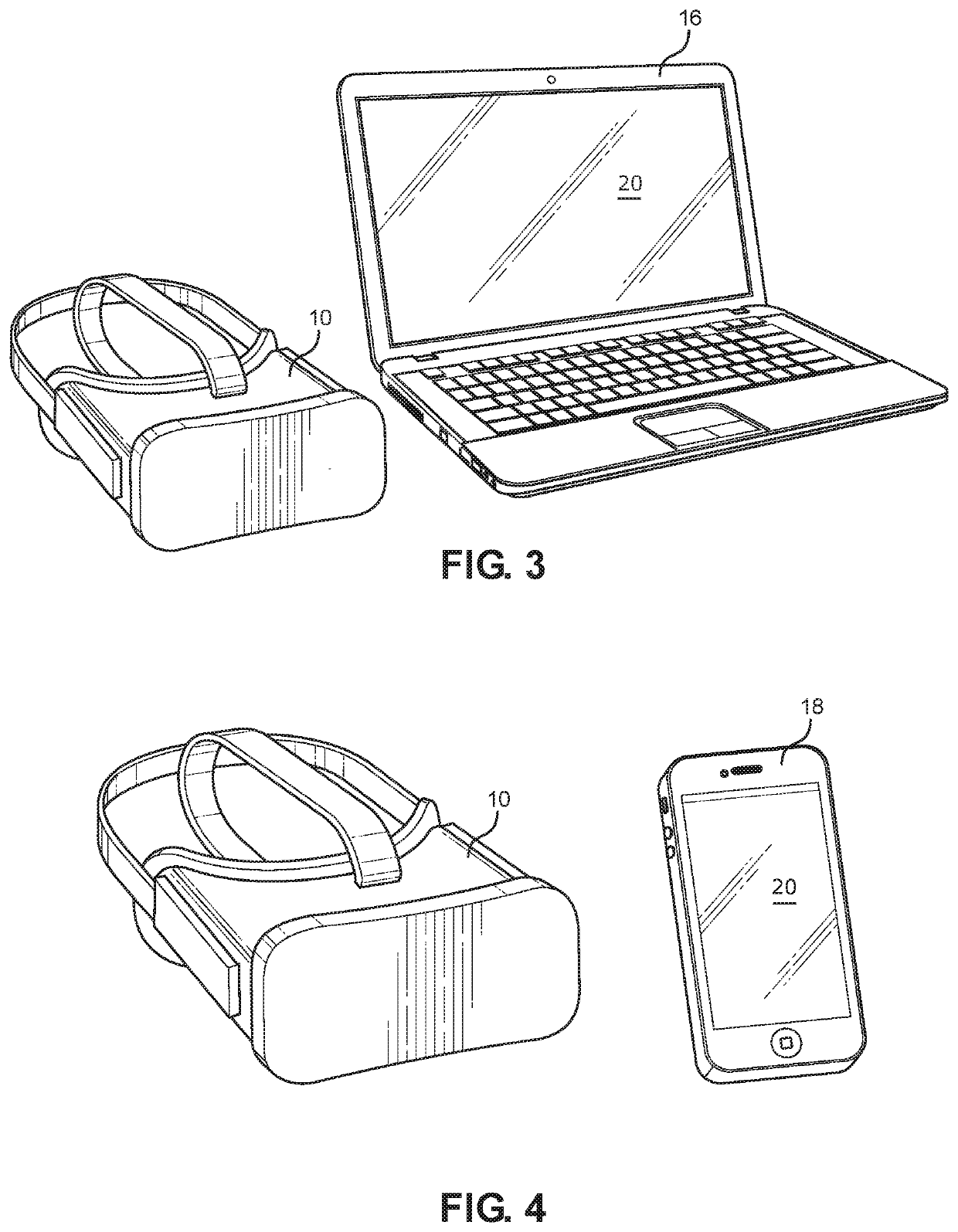
[0015]Broadly, an embodiment of the present invention provides a visual field-testing system incorporating a virtual reality output device operatively associated with a central fixation standard / static automated perimetry visual field test. The virtual reality output device is embodied in goggles providing stationary high design technology enabling a fixed axial length from the lens of each eye being tested, producing highly accurate and repeatable testing results.

[0016]Referring now to FIGS. 1 through 4 the present invention may include at least one computer device 16 or 18 with a user interface. The computing device 16 or 18 m...


PUM


Abstract

A visual field-testing system is provided. The visual field-testing system include a method utilizing a virtual reality output device operatively associated with a central fixation standard / static automated perimetry visual field test. The virtual reality output device is embodied in goggles providing stationary high design technology enabling a fixed axial length from the lens of each eye being tested, producing highly accurate and repeatable testing results.

Description

CROSS-REFERENCE TO RELATED APPLICATION[0001]This application claims the benefit of priority of U.S. provisional application No. 62 / 637,433, filed 2 Mar. 2018, the contents of which are herein incorporated by reference.BACKGROUND OF THE INVENTION[0002]The present invention relates to visual field-testing systems and methods and, more particularly, a visual field-testing system incorporating a virtual reality output device.[0003]Visual field testing is an extremely important tool for diagnosis of glaucoma, stroke, macular degeneration, multiple sclerosis, drug toxicity, etc. The assessment of peripheral vision in ophthalmology currently uses a large bulky visual field machine—the gold standard machine—called a “Humphrey.” Made by Zeiss.[0004]The Humphrey visual field test requires patients to be mobile so as to access the Humphrey equipment in a room dedicated to housing the Humphrey visual field machinery. The patient also needs to be responsive and alert in order to maintain a good ...

Claims


Application Information

Patent Timeline
IPC IPC(8): A61B3/024A61B3/18A61B3/00G02B27/01
CPCA61B3/18A61B3/005G02B27/017A61B3/0025A61B3/024G02B2027/0141
Inventor LEWIS, TRACEY LYNNE
Owner LEWIS TRACEY LYNNE
Learn More