
Methods and systems for heart failure prevention and treatments using ultrasound and leadless implantable devices

a technology of implantable devices and methods, applied in the field of prevention and treatment of heart failure, can solve the problems of deleterious rv apex location, and achieve the effect of preventing heart failur

Active Publication Date: 2019-11-21
EBR SYST
View PDF0 Cites 1 Cited by
  • Summary
  • Abstract
  • Description
  • Claims
  • Application Information

AI Technical Summary

Benefits of technology

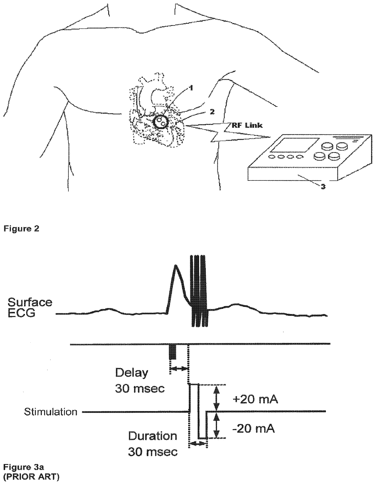
[0009]Second, the indications for permanent cardiac pacemaker implantation have greatly expanded to include the treatment of heart failure by pacing both the left and right ventricle, called cardiac resynchronization therapy (CRT) or bi-ventricular pacing. Randomized clinical trials have shown significant morbidity and mortality benefits with bi-ventricular pacing, especially when combined with an implantable cardioverter defibrillator (ICD). As described in co-pending application Ser. No. 11 / 315,023 (Attorney Docket No. 021834-000820US), and Ser. No. 11 / 315,524 (Attorney Docket No. 021834-001010US), a method of cardiac stimulation uses one or more implantable acoustic receiver-stimulators for cardiac stimulation, along with an implanted or externally-applied ultrasound controller-transmitter. Using this leadless system to avoid lead limitations and complications and gain other potential advantages as described in the co-pending applications. CRT therapy is applied to optimal single or multiple sites in the left or right heart and most notably endocardial left ventricular sites.
[0013]One example of a CCM device is an Optimizer™ II (Impulse Dynamics, Israel). These have been implanted in patients and have been shown to improve cardiac function (Pappone et al., Stix et al.). This device employs one commercially available right atrial lead used for sensing only, and 2 commercially available transvenous bipolar active fixation leads implanted in the RV septum used for sensing a local electrogram and delivery of non-excitatory electrical current.
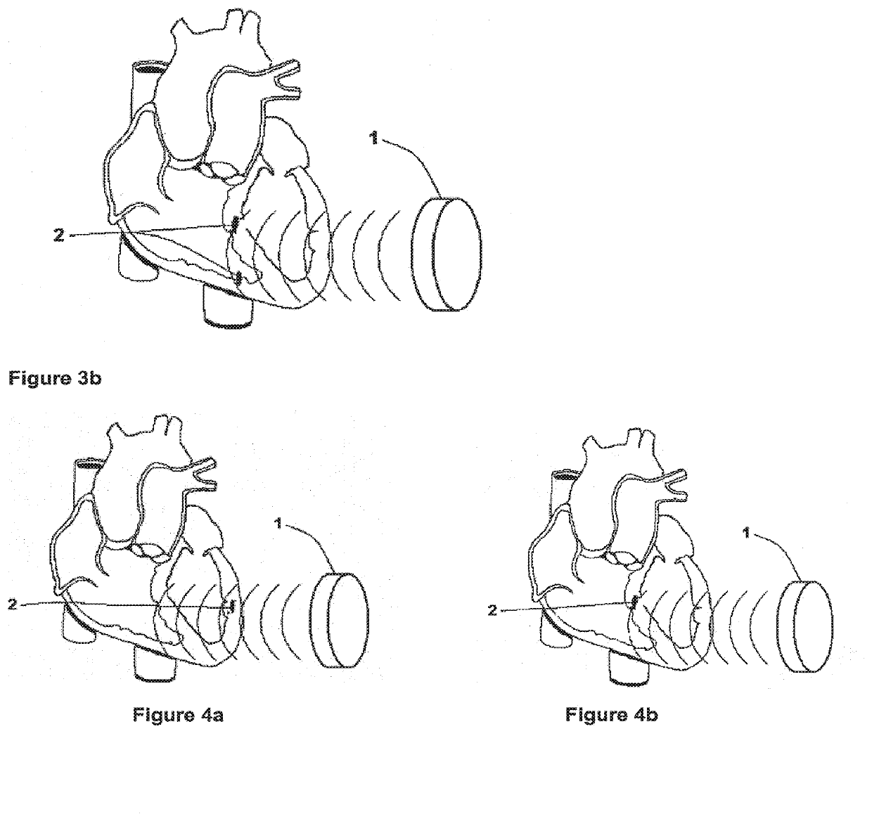
[0016]Fourth, the concept of selective site pacing to initiate a preferred pattern of cardiac activation and / or mechanical contraction has been recently put forth to prevent heart failure in patients needing permanent pacing for bradycardia indications. Traditionally, the standard ventricular site for stimulation has been the RV apex for reasons of lead stability and ease of implantation. However, recent randomized clinical trials of patients requiring bradycardia pacing (DAVID and PAVE) have lead to the conclusion that the RV apex location is deleterious. The concept of selective site pacing has emerged, and has led to the reevaluation of all traditional pacing sites. New stimulation sites being evaluated require the use of non-passive fixation tips and more precise implant techniques. The ideal site(s) may be within the left ventricle in areas inaccessible using transvenous leads from within the coronary sinus. Selective site left ventricular or right ventricular stimulation alone may provide improved heart functioning or prevention of heart failure without the need for bi-ventricular stimulation. It would be desirable to provide selective site pacing with previously referred to leadless methods and systems using one or more implantable acoustic receiver-stimulators for cardiac stimulation, along with an implanted or externally-applied ultrasound controller-transmitter. The receiver-stimulator would be implanted in the left and / or right ventricle at one or more locations that initiate a preferred pattern of cardiac activation and / or mechanical contraction.
[0018]Thus, it would further be desirable to provide an implantable device that combines the beneficial effects of direct application of ultrasound energy to cardiac tissue with the beneficial effects of a leadless electrical delivery device for cardiac resynchronization stimulation therapy, cardiac contractility modulation therapy, and / or selective site pacing therapy in order to improve cardiac function in heart failure patients or to prevent heart failure in other patients.

Problems solved by technology

However, recent randomized clinical trials of patients requiring bradycardia pacing (DAVID and PAVE) have lead to the conclusion that the RV apex location is deleterious.

Method used


Image

  • Methods and systems for heart failure prevention and treatments using ultrasound and leadless implantable devices
  • Methods and systems for heart failure prevention and treatments using ultrasound and leadless implantable devices
  • Methods and systems for heart failure prevention and treatments using ultrasound and leadless implantable devices

Examples


Embodiment Construction

[0039]The present invention relies on a controller-transmitter device to deliver ultrasound energy to cardiac tissue to directly improve cardiac function and / or to energize one or more implanted receiver-stimulator devices that transduce the ultrasound energy to electrical energy to perform excitatory and / or non-excitatory treatments for heart failure. The acoustic energy can be applied as a single burst or as multiple bursts with appropriate selection of the following parameters:

ParameterValue RangeUltrasound frequency20 kHz-5 MHzUltrasound Burst Duration 0.1 [LS-100 mSDuty Cycle0.001-6.0%Mechanical Index

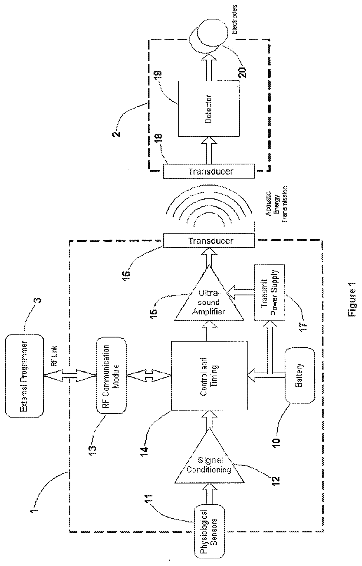
[0040]FIG. 1 is a block diagram of the present invention. An implantable controller-transmitter device 1 contains an ultrasound transducer 16 (or multiple transducers) of appropriate size(s) and aperture(s) to generate sufficient acoustic power to achieve the desired heart failure therapy. The transducer(s) 16 within the controller-transmitter device 1 are constructed of specific d...


PUM


Abstract

The present invention relies on a controller-transmitter device to deliver ultrasound energy into cardiac tissue in order to directly improve cardiac function and / or to energize one or more implanted receiver-stimulator devices that transduce the ultrasound energy to electrical energy to perform excitatory and / or non-excitatory treatments for heart failure. The acoustic energy can be applied as a single burst or as multiple bursts.

Description

CROSS-REFERENCES TO RELATED APPLICATIONS[0001]The present application is a divisional of U.S. patent application Ser. No. 12 / 829,183 (Attorney Docket No. 41567-713.401), filed Jul. 1, 2010, now U.S. Pat. No. 9,333,364, which is a divisional of U.S. patent application Ser. No. 11 / 468,002 (Attorney Docket No. 41567-713.201), filed Aug. 29, 2006, now U.S. Pat. No. 7,765,001, which claims the benefit of provisional U.S. Application No. 60 / 713,241 (Attorney Docket No. 41567-713.101), filed Aug. 31, 2005, the full disclosures of which are incorporated herein by reference.[0002]The disclosure of this application is also related to non-provisional application Ser. No. 11 / 315,023 (Attorney Docket No. 41567-708.201), filed on Dec. 21, 2005, which claims priority to provisional application 60 / 689,606 (Attorney Docket No. 41567-708.102) filed on Jun. 9, 2005, and to non-provisional application Ser. No. 10 / 869,631 (Attorney Docket No. 41567-705.201), filed on Jun. 15, 2004, the full disclosures ...

Claims


Application Information

Patent Timeline
Patent Type & Authority Applications(United States)
IPC IPC(8): A61N1/362A61N1/378A61N7/00
CPCA61N1/3787A61N7/00A61N1/362A61N1/3627A61N1/37205A61N2007/0004
Inventor ECHT, DEBRA S.RILEY, RICHARD E.COWAN, MARK W.BRISKEN, AXEL F.
Owner EBR SYST
Learn More