

Machine tool
a technology of machine tools and tools, applied in the field of machines, can solve the problems of accuracy problems in the operation of the machine, breakage or separation of certain components and associated safety problems, breakage or separation, etc., and achieve the effect of simple and reliable design, and improvement of machining accuracy and/or safety
- Summary
- Abstract
- Description
- Claims
- Application Information
AI Technical Summary
Benefits of technology
Problems solved by technology
Method used
Image

Examples
Embodiment Construction
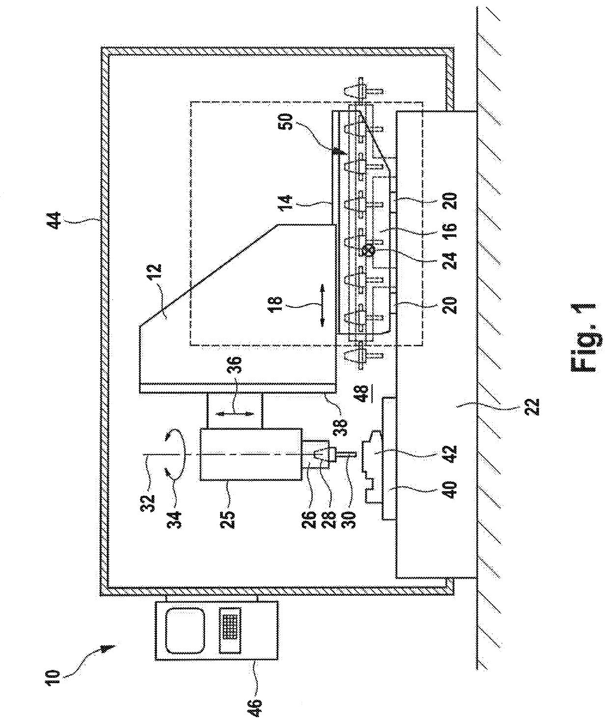
[0087]FIG. 1 illustrates, in a schematic side view that is not to scale, a machine tool denoted overall by reference numeral 10.
[0088]The machine tool 10 has a traveling column 12, which is arranged by a first slide guide 14 on a cross piece 16. The traveling column 12 can be traversed on the cross piece 16 with the aid of the first slide guide 14 in the direction of an axis which is usually referred to as the y axis and is here illustrated symbolically by an arrow 18. It is self-evident that the traveling column 12 is traversed by motor on the first slide guide 14, although a corresponding drive unit is not illustrated here for reasons of clarity.
[0089]The cross piece 16 is supported on a machine frame 22 via a second slide guide 20. The second slide guide 20 allows movement of the cross piece 16 along a second axis, which is here indicated by reference numeral 24. Reference numeral 24 denotes the so-called X axis. It is self-evident that the movement of the cross piece 16 on the s...
PUM
 Abstract
Description
Claims
Application Information