
Cutting module of cutting machine for window covering

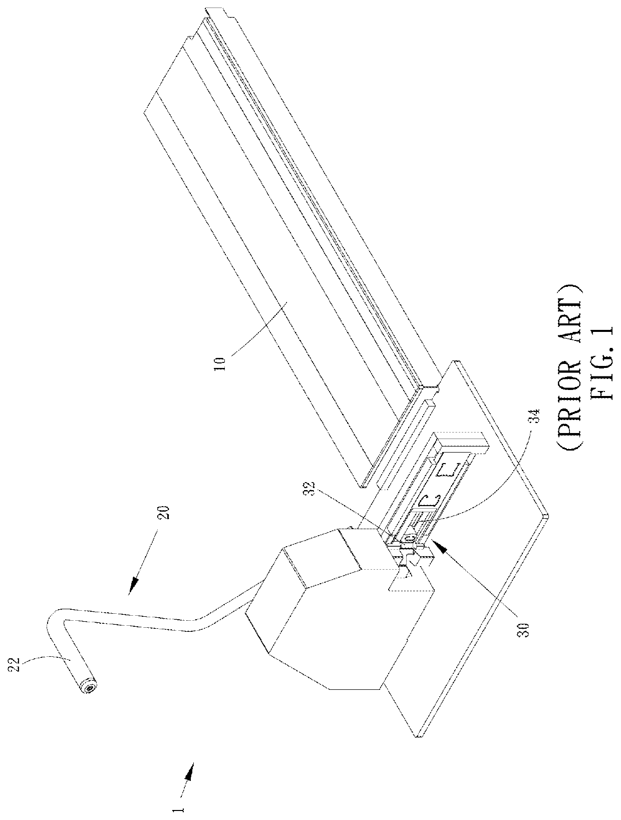
a cutting machine and window covering technology, applied in the field of window coverings, can solve the problems of not being able to fit windows of all kinds of sizes, not being able to display windows, inconvenient to change and replace molds, etc., and achieve the effect of uniform trimming

Active Publication Date: 2019-11-21
NIEN MADE ENTERPRISE CO LTD
View PDF6 Cites 0 Cited by
  • Summary
  • Abstract
  • Description
  • Claims
  • Application Information

AI Technical Summary

Benefits of technology

The design prevents covering materials from moving when they are being cut, ensuring even trimming. This is achieved by using a single through hole to cover materials of different sizes.

Problems solved by technology

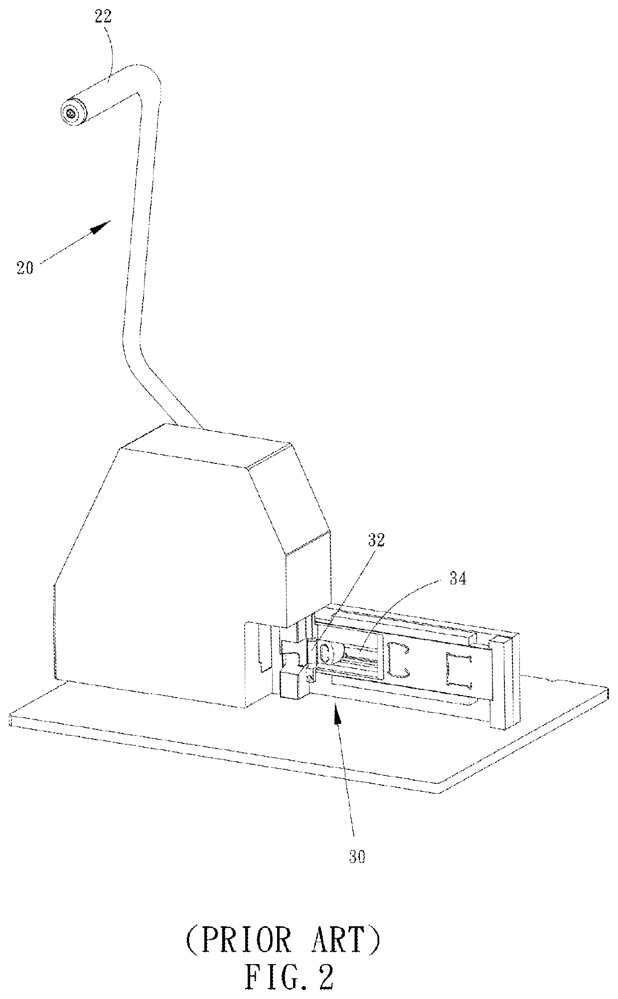
Generally speaking, the window coverings displayed in home accessories and furniture stores are manufactured by factories, which have limited specifications, and therefore would not be ready to be installed for windows of all kinds of sizes.
However, it is inconvenient to change and replace molds.
Furthermore, the molds which are not in use may get lost, and there are possibilities that the selection among multiple molds may go wrong, resulting in inferior cuttings.
On the other hand, enlarging the mold leads to a bulky cutting machine, which occupies more room, hindering the arrangement of available space and the convenience of operating the cutting machine.
Therefore, the above two solutions are not so feasible.
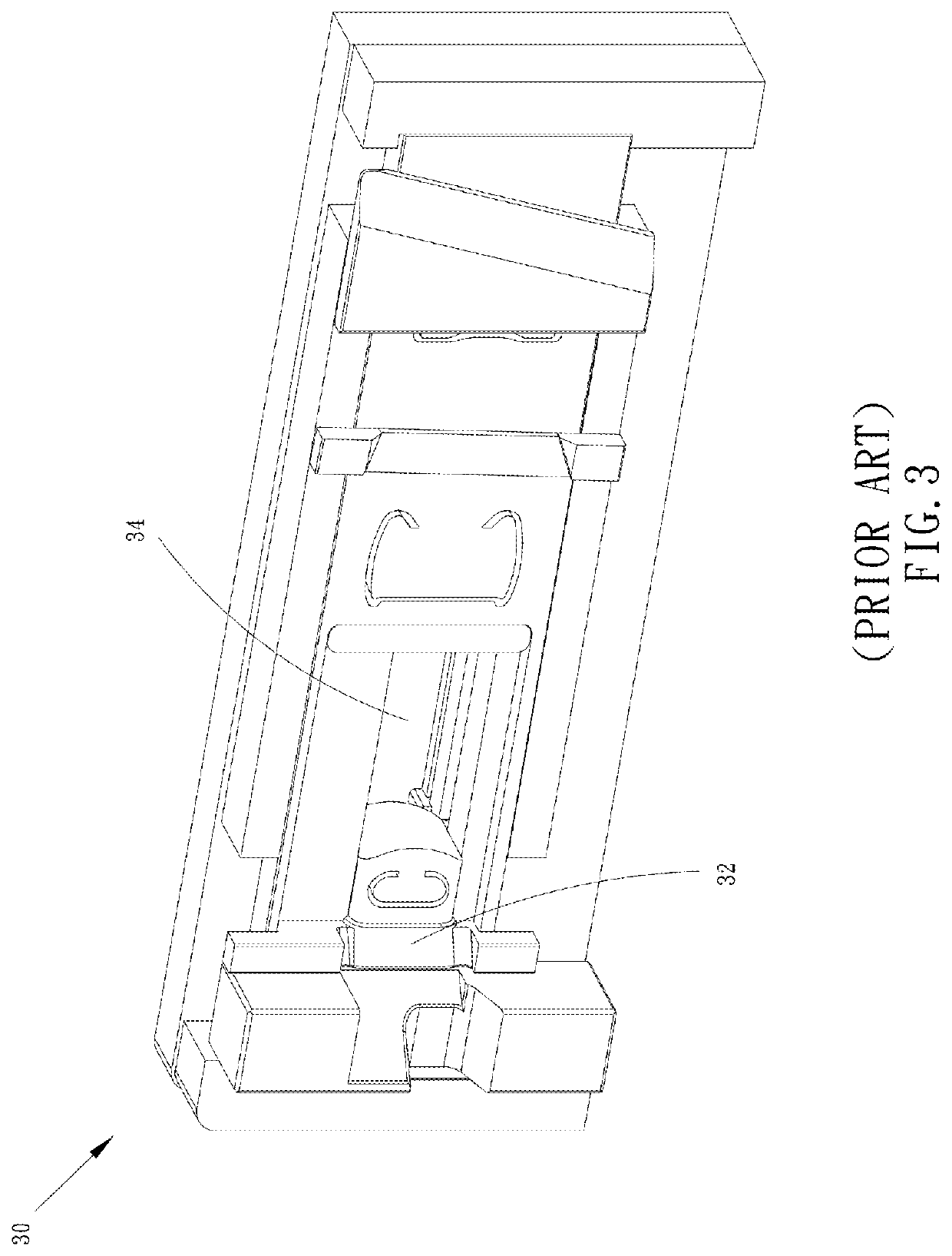
If there is only one large through hole provided, it would not be able to firmly hold slats of smaller sizes, which may cause some of the slats to slightly move as being pressed by the blade during the cutting process, producing uneven cuttings.
But if the size of the through hole is too large for the slats, the slats may be placed at a bias position, or may slide during the cutting.
As a result, the slats may not be cut evenly, or may only have a chamfer cut out on one side thereof, which would greatly reduce the quality of the finished products.

Method used


Image

  • Cutting module of cutting machine for window covering
  • Cutting module of cutting machine for window covering
  • Cutting module of cutting machine for window covering

Examples


Embodiment Construction

[0024]A cutting machine 2, which is applied with a cutting module 100 of a first embodiment of the present invention, is illustrated in FIG. 4, wherein the cutting machine 2 is adapted to trim window coverings, and also has, as the conventional cutting machine 1 mentioned above, a platform 40 and an operating module 50, wherein the platform 40 is adapted to place a window covering which is going to be trimmed, and the operating module 50 is adapted to be operated by a user, bringing the cutting module 100 into action to trim the window covering. However, the platform 40 and the operating module 50 are well-known components, and therefore we are not going to describe their details herein.

[0025]As shown in FIG. 5 and FIG. 6, which are perspective views of the cutting module 100 of the first embodiment of the present invention seen from different angles, the cutting module 100 includes a main body 110, a blade 120, and an elastic holding member. For the ease of explanation, two opposit...


PUM


Abstract

A cutting module adapted to trim a covering material of a window covering is disclosed, including a main body, a blade, and an elastic holding member. The main body has a first side, a second side, and a through hole communicating the first and the second sides, wherein the through hole can be passed through by the covering material. The blade is provided corresponding to the second side, and can be moved back and forth. The blade has a cutting edge, which passes over the through hole as the blade slides, whereby to cut off a part of the covering material beyond the second side. The elastic holding member is provided corresponding to the through hole to maintain the covering material at a predetermined position for cutting.

Description

BACKGROUND OF THE INVENTION1. Field of the Invention[0001]The present invention relates generally to a window covering, and more particularly to a cutting module of a cutting machine for window coverings.2. Description of the Prior Art[0002]Generally speaking, the window coverings displayed in home accessories and furniture stores are manufactured by factories, which have limited specifications, and therefore would not be ready to be installed for windows of all kinds of sizes. Hence, consumers usually have to measure the windows before purchasing window coverings for the windows. With the measurements, window coverings of similar sizes can be selected out and trimmed to a suitable size. In this way, the trimmed window coverings can be installed on the windows to cover the windows appropriately.[0003]To achieve the above purpose, home accessories and furniture stores are usually equipped with cutting machines, which can be operated by staffs to trim window coverings. A conventional ...

Claims


Application Information

Patent Timeline
Patent Type & Authority Applications(United States)
IPC IPC(8): B26D7/02E06B9/266B26D5/10B26D1/06B26D1/00
CPCB26D1/0006B26D7/025B26D2001/0053B26D1/06B26D5/10E06B9/266B26D2001/006
Inventor LEE, WEN-YEUNIEN, CHAO-HUNG
Owner NIEN MADE ENTERPRISE CO LTD
Learn More