Joining device for rails of a baby bed

a technology for joining devices and baby beds, which is applied in the direction of beds, kids beds, beds, etc., can solve the problems of the design of the locking means b>4/b> of the conventional baby beds, and the design of the retraction of the rail is not ideal

Active Publication Date: 2012-12-25
WONDERLAND NURSERYGOODS CO LTD
View PDF3 Cites 0 Cited by
  • Summary
  • Abstract
  • Description
  • Claims
  • Application Information

AI Technical Summary

Benefits of technology

[0010]An object of the present application is to provide a joining device for the rails of a baby bed, which can effectively prevent the situation that the fabric covering is gripped by the rail tubes and the iron plate of the joining device when the retraction operation of the rail tubes is performed.
[0015]The present invention provides a joining device for the rails of a baby bed, in which said joining device is formed as a saddle part in a -shape and characterized in that: two outer edges of an iron plate at two ends of two shorter sides of an arched portion of said joining device are processed such that they are bent downwardly so as to be formed as contact faces with a smooth arc shape, and each of the backsides of said contact faces is further subject to a trimming process so as to be formed as a smoothly trimmed face in order to prevent a possibility that a fabric covering is directly cut off or broken when the fabric covering covered on a bed frame is gripped between the rail tubes and the arched portion of said joining device, and a possibility of generating an indent due to friction or pressing since that the tube walls of said rail tubes are rammed with the two outer edges of the iron plate at the two ends of the two shorter sides of the arched portion of said joining device.
[0019]The present invention achieves an advantageous technical effect in that: in the joining device for the rails of a baby bed in accordance with the present invention, the joining device is provided with a smoothly trimmed face so as to further prevent a situation that when the baby bed is in use, a fabric covering is gripped between the rail tubes connected to the two sides of the joining device and the arched portion of the joining device as the rail tubes are extended to be in a horizontal state, and thus the fabric covering is cut off or broken.

Problems solved by technology

However, most of the designs for the retraction of the rail locking means 4 of the conventional baby bed are not ideal.

Method used


Image

  • Joining device for rails of a baby bed
  • Joining device for rails of a baby bed
  • Joining device for rails of a baby bed

Examples


Embodiment Construction

[0029]An embodiment in accordance with the present application will be described hereinafter with reference to the accompanying drawings by exemplifying an improved joining device for the rails of a baby bed.

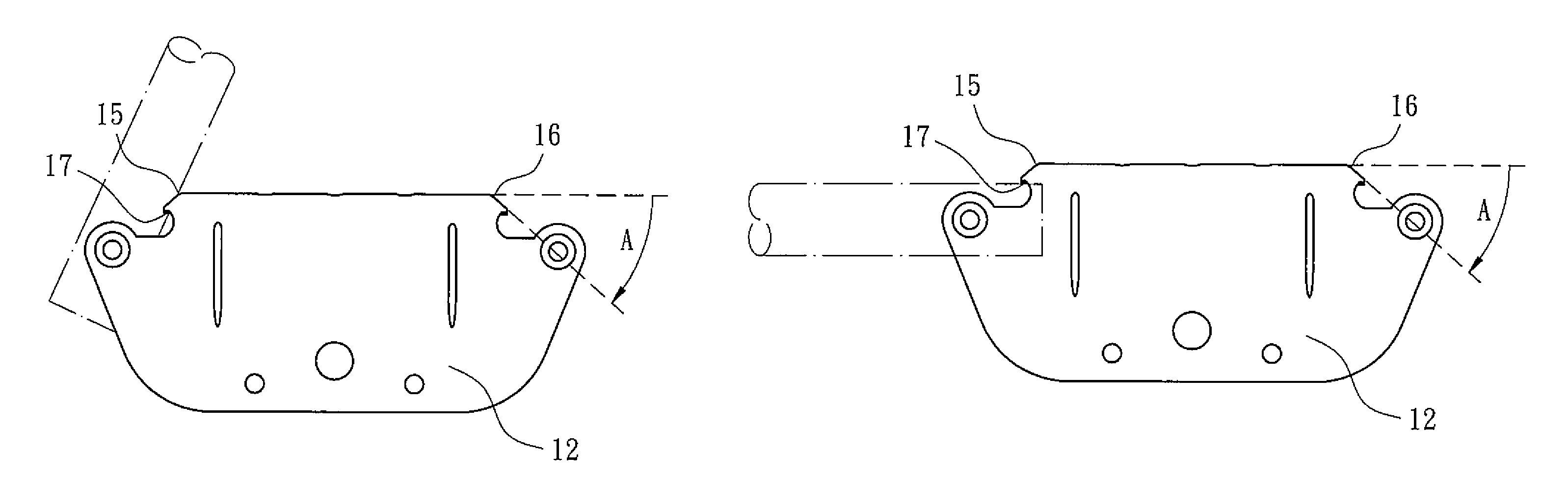
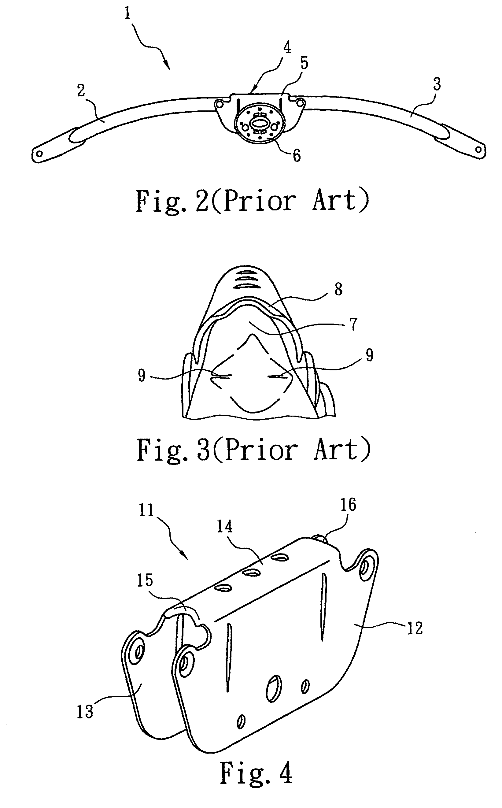
[0030]FIG. 4 is a perspective view of a joining device for the rails of a baby bed in accordance with the present application; FIG. 5 is a side view of a joining device for the rails of a baby bed in accordance with the present application; FIG. 6 is a top view of a joining device for the rails of a baby bed in accordance with the present application; and FIG. 7 is a bottom view of a joining device for the rails of a baby bed in accordance with the present application.

[0031]As shown in FIG. 4, the joining device 11 for the rails of a baby bed in accordance with the present application is, for example, made of an iron plate and integrally formed as a saddle part in a -shape (or a reversed U-shape). That is, the joining device 11 can be regarded as a -shaped saddle part formed by ...


PUM


Abstract

A joining device is provided for rails of a baby bed, in which the joining connects two adjacent rail tubes of the rail, where an end of each of the rail tubes is pivotally connected to the joining device. The joining device is formed as a saddle part in a shape having two upstanding side walls and an arched portion connected between top edges of the two side walls. The joining device further has a smooth contact face formed on each of the two sides of the arched portion and a smoothly trimmed face connected to the smooth contact face, so that the tube walls of the rail tubes are contacted with the smooth contact faces when the rail tubes are pivotally rotated close to the two sides of the arched portion.

Description

BACKGROUND OF THE INVENTION[0001]1. Field of the Invention[0002]The present invention relates to a joining device for a rail of a baby bed, and more particularly, to a joining device for a rail of a baby bed, which can prevent a fabric covering of a baby bed from being gripped between a rail tube and a connecting iron plate of the joining device when the bed frame of the baby bed is retracted.[0003]2. Description of the Related Art[0004]At present, the use of a baby bed is relatively common. FIG. 1 is a perspective view of a conventional baby bed in which a rail member 1 of the baby bed is in an extended state and covered with a fabric covering 10. FIG. 2 is a front view showing a structure of the baby bed shown in FIG. 1, in which the fabric covering 10 covered on the rail member 1 has been removed.[0005]As shown in FIG. 1, when the baby bed is in use, the bed frame (for example, the rail member) thereof is usually covered with the fabric covering. Moreover, in current designs for ...

Claims


Application Information

Patent Timeline
Patent Type & Authority Patents(United States)
IPC IPC(8): A47D7/00A47C7/00A47C23/00A47C19/00A47D13/06
CPCA47D13/063
Inventor LIN, LI-YUANWANG, HONG-GUANG
Owner WONDERLAND NURSERYGOODS CO LTD
Why Eureka
Try Eureka