
Garden Scissors

a technology for garden scissors and cutting blades, applied in the field of scissors, can solve the problems of user's pulling the driving line harder, affecting the cutting blade, and affecting the cutting blade, and achieve the effect of stabilizing the structur

Inactive Publication Date: 2019-11-28
SHANG ENTERPRISE
View PDF0 Cites 2 Cited by
  • Summary
  • Abstract
  • Description
  • Claims
  • Application Information

AI Technical Summary

Benefits of technology

The present invention provides a garden scissors that is designed to be lighter, which can help to reduce the physical burden on the user. The scissors have a pulley portion that can be pulled to rotate, which in turn causes the cutter to rotate and trim the branch. The scissors also have a flywheel portion that helps to balance the gear portion and resist the inclining force caused by the torque. The strength of the scissors is strengthened, allowing for the use of lighter materials without compromising durability. Overall, the garden scissors are designed to be lightweight and easy to use.

Problems solved by technology

However, the structure of the garden scissors mentioned above may not strong enough in heavy duty operation.
When the user tries to cut a bough or a larger branch, the user may pull the driving line harder, exerting larger force on the blade.
Therefore, a larger torque will be generated on the wheel, leading swaying or inclining of the wheel.
The garden scissors could be damaged or destroyed due to the swaying or inclining caused by the unstable structure and the force exerted thereon.
However, such material and structure are usually weighted heavier.
When users lift the scissors by its rear end to reach and to trim the branches, the weight of the scissors can be a heavy burden to the users.

Method used


Image

  • Garden Scissors
  • Garden Scissors
  • Garden Scissors

Examples


Embodiment Construction

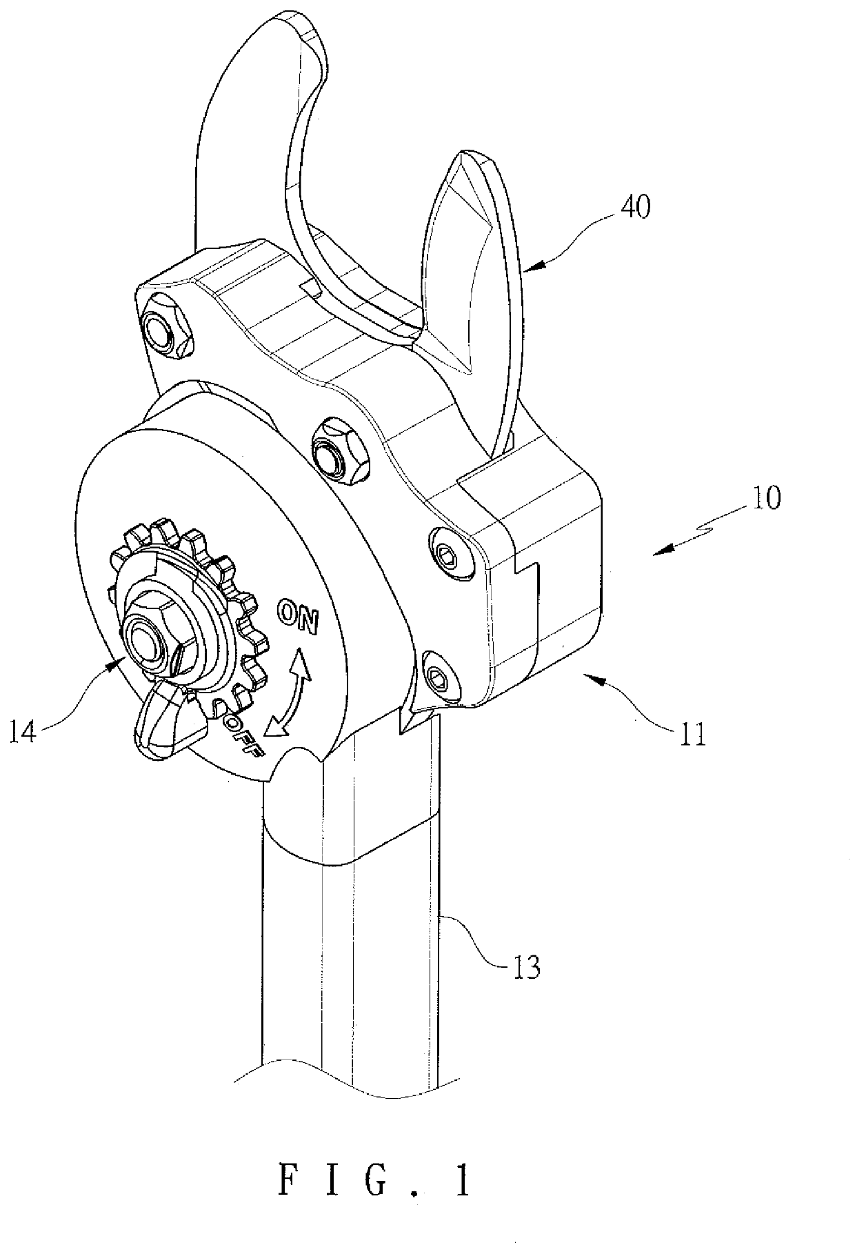
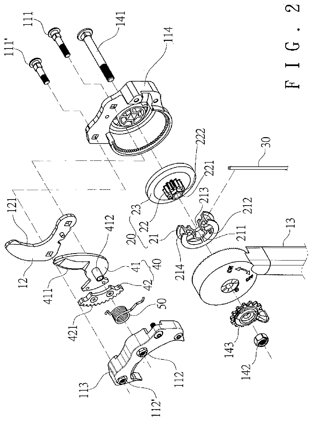
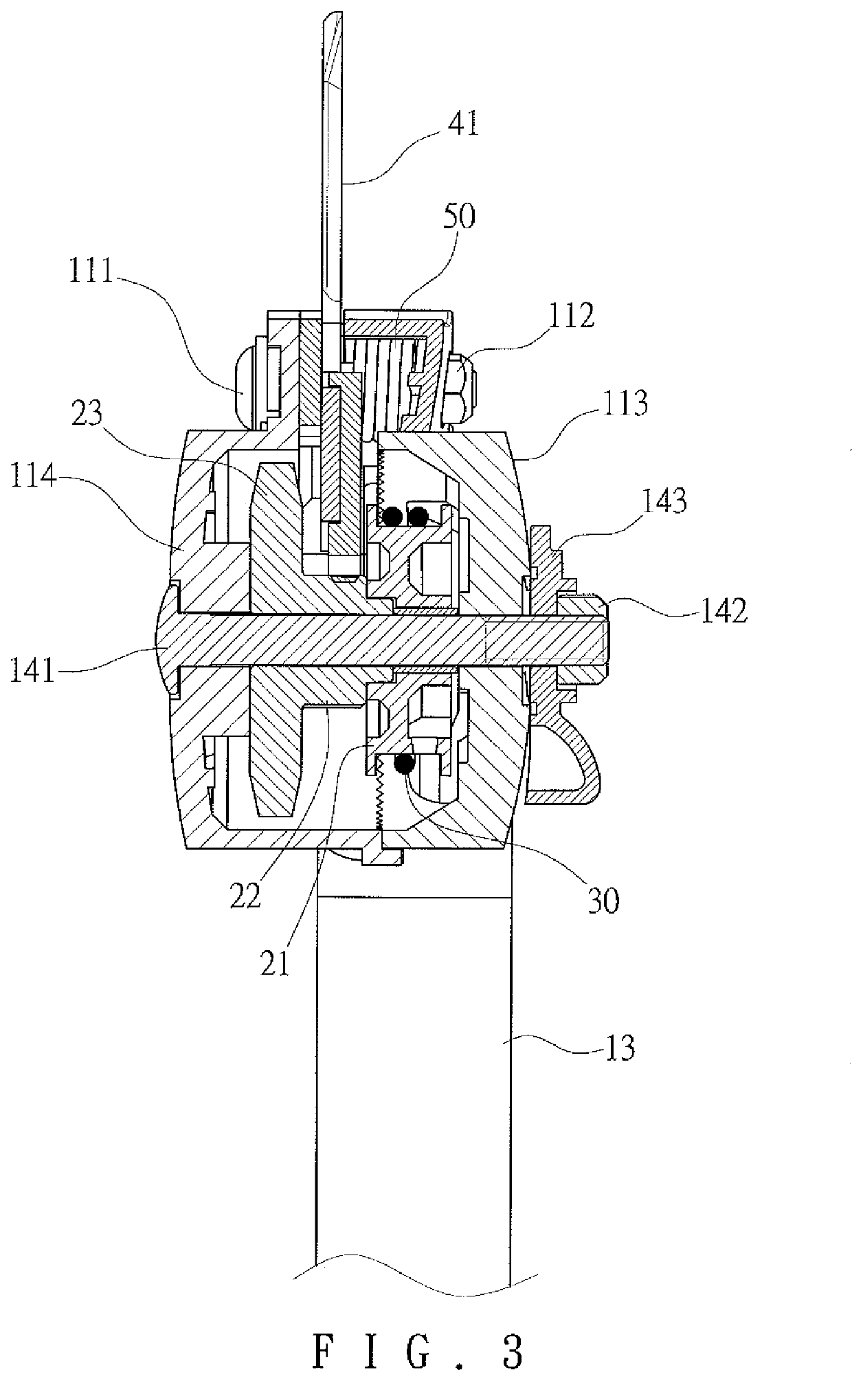
[0018]The present embodiment reveals a garden scissors which can be used for trimming branches. Please refer to FIG. 1 to FIG. 4 for a first embodiment of the present invention. The garden scissors of the embodiment includes a chassis 10, a transmission mechanism 20, a driving line 30, a cutter 40, and an elastic member 50.

[0019]The chassis 10 includes a head portion 11, a fixed blade 12, a handle portion 13, and an axial portion 14. The head portion includes screws 111, 111′, nuts 112, 112′, a left sub-portion 113, and a right sub-portion 114. The left sub-portion 113 is fixed to the right sub-portion 114 by the screws 111, 111′ and the nuts 112, 112′. The fixed blade 12 is clipped and fixed between the left sub-portion 113 and the right sub-portion 114. The fixed blade 12 extends through the seam between the left sub-portion 113 and the right sub-portion 114 and extends upwardly, forming a fixed cutting edge 121 thereon. The handle portion 13 is configured as a long pole. The axia...


PUM


Abstract

A garden scissors of the present invention includes a chassis, a transmission mechanism, a driving line, and a cutter. The transmission mechanism is rotatably disposed to the chassis. The transmission mechanism includes a pulley portion, a gear portion, and a flywheel portion, which rotate simultaneously. The gear portion is located between the pulley portion and the flywheel portion. An end of the driving line is rolled on the pulley portion. The cutter has an engagement portion engaged with the gear portion. Thus, the pulley portion, the gear portion, and the cutter are rotated when the driving line is pulled away from the pulley portion, driving the cutter to pivot to cut branches. Therefore, the flywheel portion of the transmission mechanism laying on the chassis, supporting and balancing the force exerted on and the movements of the pulley portion and the gear portion. The structure of the garden scissors is then stabilized.

Description

BACKGROUND OF THE INVENTIONField of the Invention[0001]The present invention relates to a scissors, in particularly used for trimming branches.Description of the Prior Art[0002]Currently, some garden scissors are made as if a long pole so as to extend to the branches and twigs of trees or shrubs for trimming the branches and twigs. For example, U.S. Pat. No. 6,748,663 reveals a lopper for trimming. Such garden scissors, or named as a lopper, is mainly configured as a long pole with a rotatable blade disposed at the front end thereof. The blade is connected to a chain. The opposite end of the chain is connected to a wheel which a driving line is wounded around. The driving line extends to the rear end of the garden scissors. User may pull the driving line from the rear end to rotate the wheel, driving the blade to rotate via the chain for trimming.[0003]However, the structure of the garden scissors mentioned above may not strong enough in heavy duty operation. In view of the force tr...

Claims


Application Information

Patent Timeline
IPC IPC(8): A01G3/053A01G3/08
CPCA01G3/053A01G3/085A01G3/0255A01G3/033
Inventor LIN, CHU-LAN
Owner SHANG ENTERPRISE
Learn More