Clamp for use with an impact tool

Active Publication Date: 2019-11-28
MACDONALD LUKE DOUGLAS +1
View PDF5 Cites 2 Cited by
  • Summary
  • Abstract
  • Description
  • Claims
  • Application Information

AI Technical Summary

Benefits of technology

[0009]For purposes of summarizing the invention, certain aspects, advantages, and novel features of the invention have been described herein. It is to be understood that not necessarily all such advantages may be achieved in accordance with any one particular embodiment of the invention. Thus, the invention may be embodied or carried out in a manner that achieves or optimizes one advantage or group of advantages as taught

Problems solved by technology

It has been found that many prior art devices are deficient and cannot withstand the stresses placed on the same when subjected to

Method used


Image

  • Clamp for use with an impact tool
  • Clamp for use with an impact tool
  • Clamp for use with an impact tool

Examples


Embodiment Construction

[0021]As discussed above, embodiments of the present disclosure relate to work holders and more particularly to a clamp for use with an impact tool as used to improve a means for handling clamp with socket fastener means to maintain a firm grip, particularly advantageous for while working at heights.

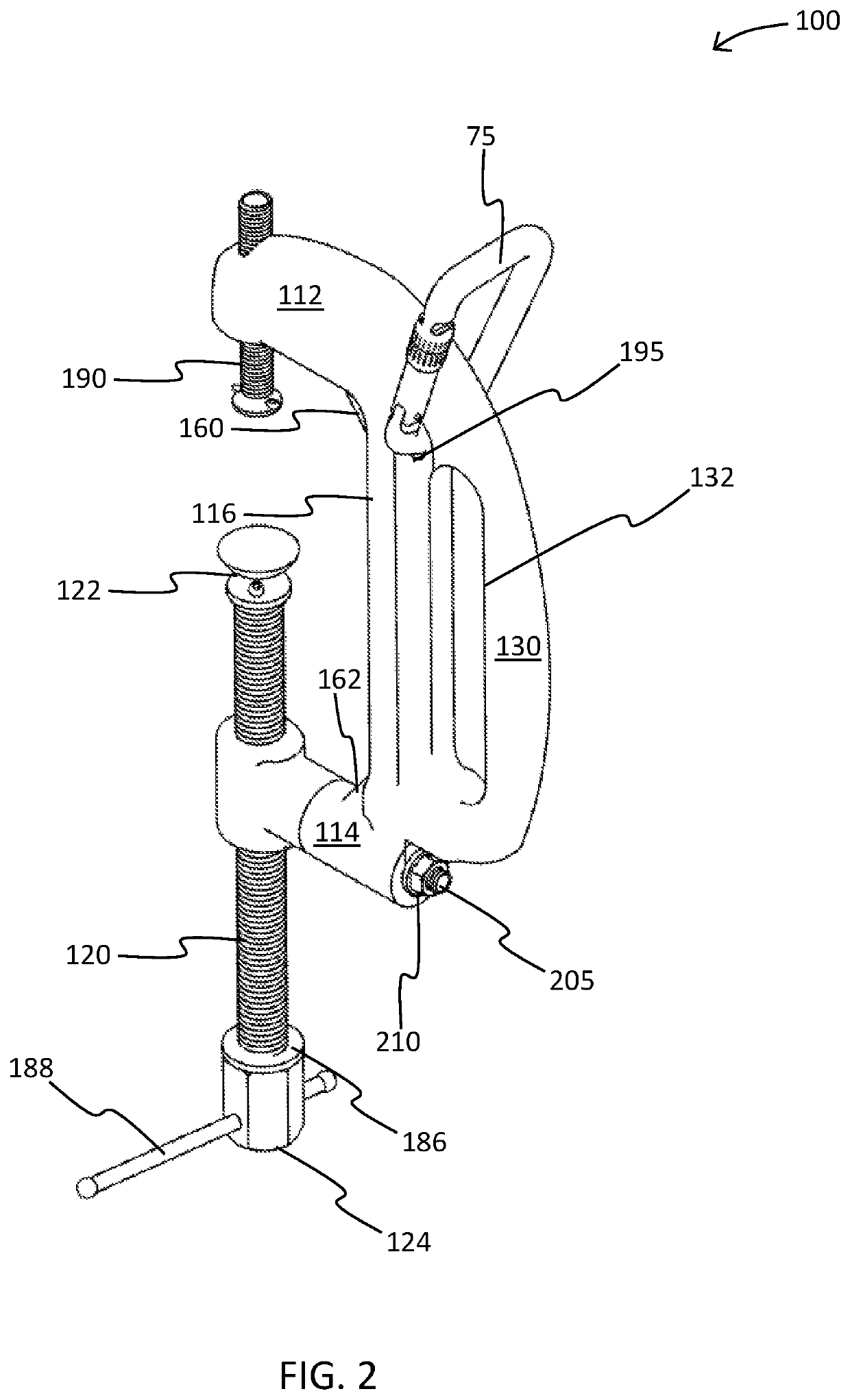
[0022]Generally, the improved “C” clamp, also known as “Kwick Klamp”, may comprise an ergonomic handle, a pair of weld gussets for reinforcing the structural integrity of the clamp, and a screw for adjusting use of the clamp with an impact tool (such as a drill or the like).

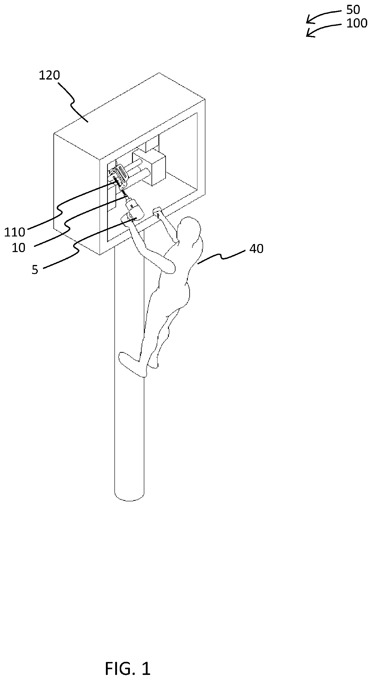
[0023]Referring now more specifically to the drawings by numerals of reference, there is shown in FIGS. 1-4B, various views of a clamp 100 for use with an impact tool 5. FIG. 1 shows a clamp 100 for use with an impact tool 5 during an ‘in-use’ condition 50 by a user 40, according to an embodiment of the present disclosure.

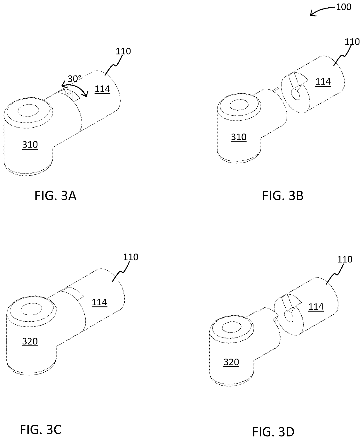
[0024]As illustrated, the clamp 100 for use with an impact tool 5 may include a frame 110. The fr...


PUM


Abstract

A clamp for use with an impact tool; the clamp having a nut for use with impact tools includes a screw on top, a safety handle, and a hole for carabiner clip. In use, a user adjusts the top screw to a length option desired, such that it doesn't slide onto object to be clamped. The clamp further comprises a grip on the safety handle. The clamp provides faster and more efficient use when using an impact tool.

Description

BACKGROUND OF THE INVENTION[0001]The following includes information that may be useful in understanding the present disclosure. It is not an admission that any of the information provided herein is prior art nor material to the presently described or claimed inventions, nor that any publication or document that is specifically or implicitly referenced is prior art.1. FIELD OF THE INVENTION[0002]The present invention relates generally to the field of work holders and more specifically relates to a clamp with socket fastener means.2. DESCRIPTION OF RELATED ART[0003]Throughout the ages, many tools, devices, and fixtures have been proposed and used for clamping and securement of workpieces. It has been found that many prior art devices are deficient and cannot withstand the stresses placed on the same when subjected to high clamping torque common when tubes to be welded are misaligned, a common occurrence in boiler, refinery and other applications. Heating and cooling cycles common in w...

Claims


Application Information

Patent Timeline
IPC IPC(8): B25B5/10
CPCB25B5/147B25B5/101B23K37/0533B25B21/02B23K2101/06B23K37/0435
Inventor MACDONALD, LUKE DOUGLASCANNING, DAMIEN WILLIAM
Owner MACDONALD LUKE DOUGLAS
Why Eureka
Try Eureka