System and method for controlling degreasing of a kitchen ventilation system

a technology for ventilation systems and kitchens, applied in the direction of dirt cleaning, cleaning hollow objects, domestic heating details, etc., can solve the problems of increasing the risk of fire, reducing the effectiveness of the kitchen ventilation system, and uncomfortable kitchen environmen

Inactive Publication Date: 2019-12-05
INTELLINOX
View PDF0 Cites 1 Cited by
  • Summary
  • Abstract
  • Description
  • Claims
  • Application Information

AI Technical Summary

Benefits of technology

[0008]In an embodiment, the kitchen ventilation system comprises a duct subsystem; and injecting at least one degreasing agent within the kitchen ventilation system comprises injecting the at least one degreasing agent into the duct subsystem of the kitchen ventilation system. The at least one degreasing setpoint can comprise. a first speed of an airflow subsystem of the kitchen ventilation system and a second speed of the airflow subsystem of the kitchen ventilation system; and operating the at least one subsystem of the kitchen ventilation system can comprise: operating the airflow subsystem at the first speed while injecting the degreasing agent during a first portion of the degreasing time interval; and operating the airflow subsystem at the second speed while injecting the degreasing agent during a second portion of the degreasing time interval. The second speed of the airflow subsystem of the kitchen ventilation system can be greater than the first speed of the airflow subsystem. Operating the airflow subsystem of the kitchen ventilation system at the first speed while injecting the degreasing agent can be effective for providing degreasing action at an inlet region of the duct subsystem. The first speed can be a low speed or an off state of the airflow subsystem of the kitchen ventilation system. The airflow subsystem can be operated at the first speed for a post-injection time subinterval of

Problems solved by technology

These trapped emissions decrease the effectiveness of the kitchen ventilation system 1 as well as introduce

Method used


Image

  • System and method for controlling degreasing of a kitchen ventilation system
  • System and method for controlling degreasing of a kitchen ventilation system
  • System and method for controlling degreasing of a kitchen ventilation system

Examples


Embodiment Construction

[0050]It will be appreciated that, for simplicity and clarity of illustration, where considered appropriate, reference numerals may be repeated among the figures to indicate corresponding or analogous elements or steps. In addition, numerous specific details are set forth in order to provide a thorough understanding of the exemplary embodiments described herein. However, it will be understood by those of ordinary skill in the art that the embodiments described herein may be practiced without these specific details. In other instances, well-known methods, procedures and components have not been described in detail so as not to obscure the embodiments described herein. Furthermore, this description is not to be considered as limiting the scope of the embodiments described herein in any way but rather as merely describing the implementation of the various embodiments described herein.

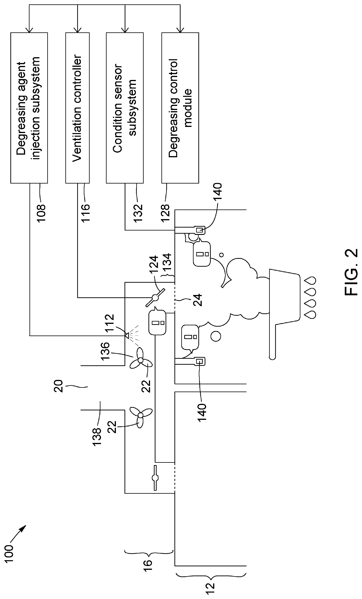
[0051]FIG. 2 illustrates a schematic diagram of a degreasing-capable kitchen ventilation system 100 acc...


PUM


Abstract

A method and system for degreasing a kitchen ventilation system includes determining degreasing setpoint(s) for a degreasing time interval, injecting degreasing agent within the kitchen ventilation system during the degreasing time interval and operating subsystem(s) of the kitchen ventilation system in accordance with the degreasing set point(s). The method and system can also include sensing operating condition(s) within the kitchen ventilation system, determining degreasing parameter(s) based on the sensed operation(s) and injecting degreasing agent with the kitchen ventilation system according to the degreasing parameter(s). Operating condition(s) can also be tracked over time to schedule degreasing at a future time. Safe degreasing conditions can also be detected prior to any injection of the degreasing agent.

Description

CROSS-REFERENCE TO RELATED APPLICATIONS[0001]The present application claims priority from U.S. provisional patent application No. 62 / 445,961, filed on Jan. 13, 2017 and entitled “SYSTEM AND METHOD FOR CONTROLLING DEGREASING OF A KITCHEN VENTILATION SYSTEM”, the disclosure of which is hereby incorporated by reference in its entirety.TECHNICAL FIELD OF THE INVENTION[0002]The present disclosure generally relates to a system and method for controlling degreasing of a kitchen ventilation system, and more particularly, a system and method in which a degreasing agent is intermittently injected into the kitchen ventilation system and in which the injection of the degreasing agent and / or the operation of the kitchen ventilation system is controlled.BACKGROUND[0003]A kitchen ventilation system is adapted for treating air from kitchens. In particular, the kitchen ventilation system seeks to remove emissions introduced from cooking, such as grease, smoke and odors. A kitchen ventilation system ...

Claims


Application Information

Patent Timeline
IPC IPC(8): F24C15/20B08B15/02B08B9/027
CPCB08B15/02F24C15/2057B08B9/027B08B9/00F24C15/20
Inventor ROUSSEAU, MARIOCOUILLARD, DANIEL
Owner INTELLINOX
Why Eureka
Try Eureka