Projection display device

Active Publication Date: 2019-12-05
MEGA 1 CO LTD
View PDF3 Cites 0 Cited by
  • Summary
  • Abstract
  • Description
  • Claims
  • Application Information

AI Technical Summary

Benefits of technology

The invention is about a display device that can show pictures on surfaces without losing brightness. The device uses special technology to switch the direction of light beams during different periods. This allows the light beams to be directed to different surfaces and create different pictures without losing brightness. This technology is called LC lens.

Problems solved by technology

Thus, a passenger or passengers in the vehicle cannot see the virtual image, or can see the virtual image but with unacceptable image quality.
However, the micro-structure will result in image brightness loss to reduce image quality.

Method used


Image

  • Projection display device
  • Projection display device
  • Projection display device

Examples


Embodiment Construction

[0021]Reference will now be made in detail to several embodiments of the invention that are illustrated in the accompanying drawings. Wherever possible, same or similar reference numerals are used in the drawings and the description to refer to the same or like parts or steps. The drawings are in simplified form and are not to precise scale or shape.

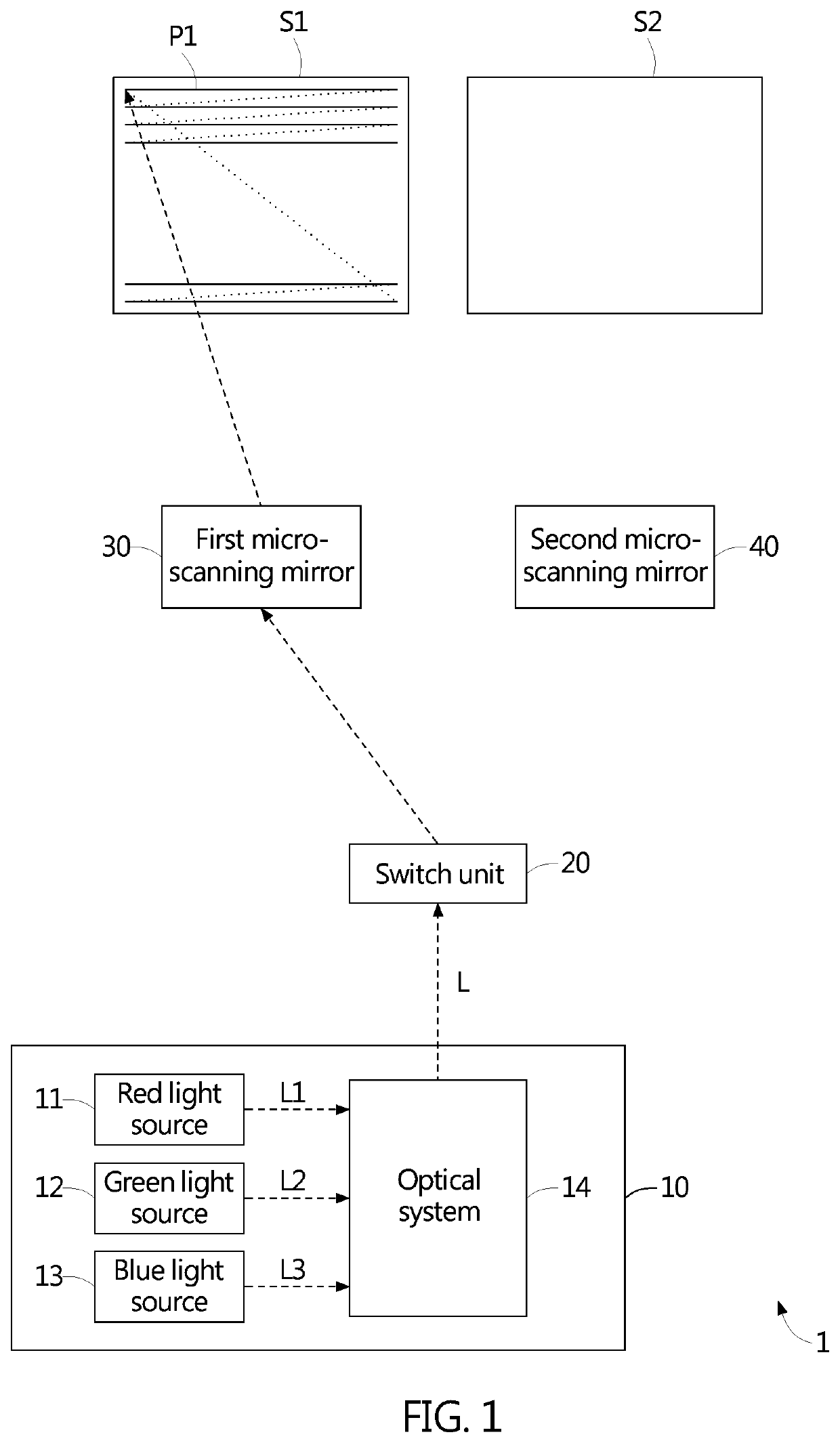
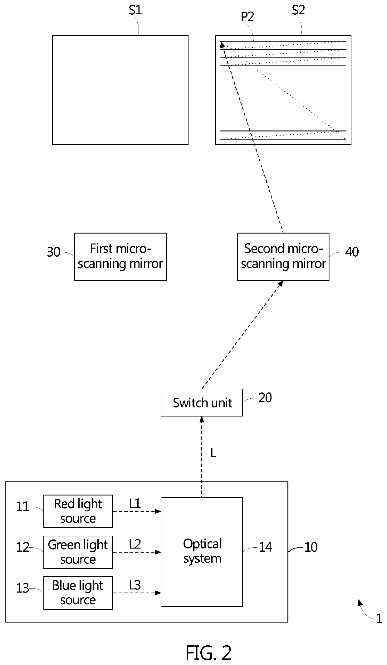
[0022]Referring to FIG. 1 and FIG. 2, FIG. 1 and FIG. 2 are schematic diagrams of a projection display device 1 scanning over two projection surfaces to form two images during two periods respectively according to an embodiment of the invention. The projection display device 1 includes a light source module 10, a switch unit 20, and micro-scanning mirrors. The light source module 10 provides a light beam L. The switch unit 20 receives the light beam L and switches a transmission direction of the light beam L to the corresponding one of the micro-scanning mirrors during each of periods. The micro-scanning mirrors cause the light beam L to...


PUM


Abstract

A projection display device includes a light source module, a switch unit, and micro-scanning mirrors. The light source module provides a light beam. The switch unit receives the light beam and switches a transmission direction of the light beam to the corresponding one of the micro-scanning mirrors during each of periods. The micro-scanning mirrors cause the light beam to scan over projection surfaces to form images. The projection display device can project the images on the projection surfaces without image brightness loss.

Description

BACKGROUND OF THE INVENTION1. Field of the Invention[0001]The invention relates to a projection display device and, more particularly, to a projection display device that can be applied to a vehicle.2. Description of the Prior Art[0002]A conventional projection display device applied to a vehicle usually only projects an image on a projection surface on a windshield of the vehicle, thereby generating a virtual image in front of the windshield to mainly provide information for a driver to see. Thus, a passenger or passengers in the vehicle cannot see the virtual image, or can see the virtual image but with unacceptable image quality. To improve this problem, an improved projection display device is developed by disposing a micro-structure such as a micro-lens array (MLA) on the projection surface on the windshield to increase the angle of view that can see the virtual image, so that the passenger or passengers in the vehicle can see the virtual image with acceptable image quality. Ho...

Claims


Application Information

Patent Timeline
IPC IPC(8): G03B21/20H04N9/31B60K35/00G02B26/12
CPCB60K2370/334G02B26/12G03B21/2066H04N9/3155B60K35/00G03B21/008H04N9/3129H04N9/3147H04N9/3188G02B27/0101G02B26/0816B60K2360/23B60K2360/334G03B21/28
Inventor WU, HANG-CHIANG
Owner MEGA 1 CO LTD
Why Eureka
Try Eureka