
Image processing apparatus, information processing apparatus, information processing method, and recording medium

a technology of information processing and image processing, applied in the field of image processing apparatus, information processing apparatus, information processing method, and recording medium, can solve the problems of undesirable display of misleading user, invalid client apparatus holding,

Active Publication Date: 2019-12-05
CANON KK
View PDF0 Cites 4 Cited by
  • Summary
  • Abstract
  • Description
  • Claims
  • Application Information

AI Technical Summary

Benefits of technology

The present invention relates to an imaging apparatus that can detect objects in images and transmit them to an information processing apparatus for further processing. The invention is designed to prevent the client apparatus from holding invalid object information. If the detection function of the detection unit is invalid with respect to a second image, the transmission unit transmits invalidity information indicating that the object is not detected with respect to the second image to the information processing apparatus. The technical effect of this invention is that it enhances the reliability and accuracy of object detection in images, especially in multiple image transmission scenarios.

Problems solved by technology

In this case, the object information that the client apparatus continues holding is invalid information after the detection function of the imaging apparatus becomes invalid.
According to the technique discussed in Japanese Patent No. 5999395, even when the detection function becomes invalid on the imaging apparatus side, the client apparatus may incorrectly determine that the object is continuously detected on the imaging apparatus side and undesirably present a display misleading a user.

Method used


Image

  • Image processing apparatus, information processing apparatus, information processing method, and recording medium
  • Image processing apparatus, information processing apparatus, information processing method, and recording medium
  • Image processing apparatus, information processing apparatus, information processing method, and recording medium

Examples


first embodiment

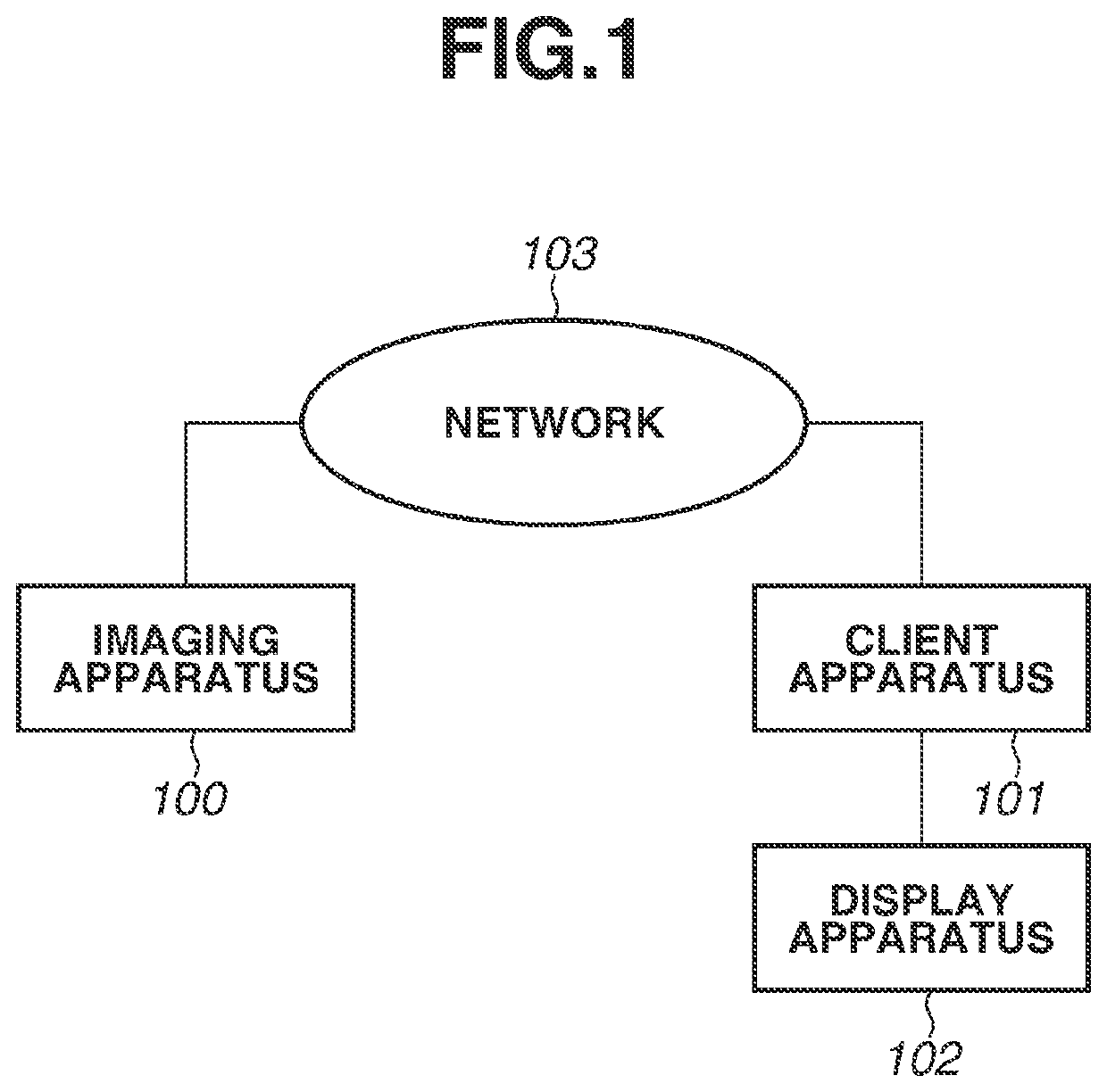
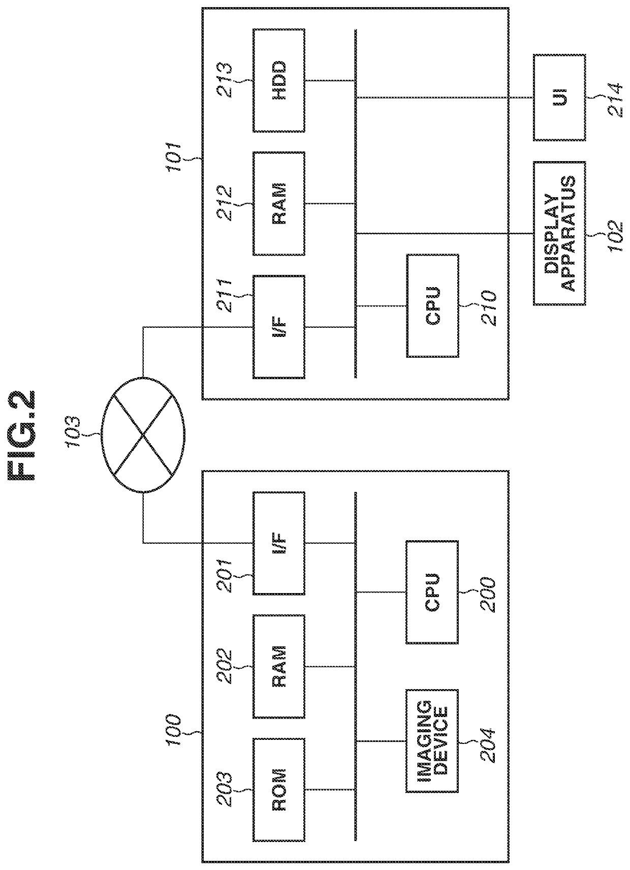
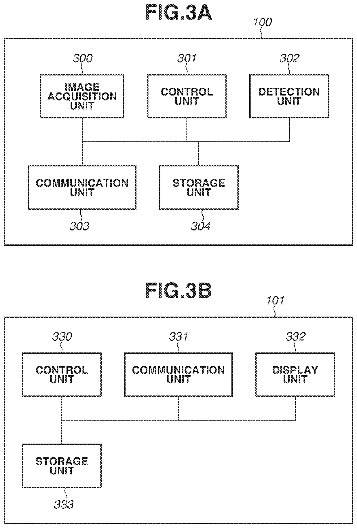
[0021]In the following description, a first embodiment will be described. FIG. 1 is a schematic view illustrating a system configuration according to the present embodiment. An imaging apparatus 100 is an apparatus that captures an image, and is, for example, a network camera or a monitoring camera capable of transmitting the image via a network 103.

[0022]A client apparatus 101 is an information processing apparatus, and is communicably connected to the imaging apparatus 100 via the network 103. The client apparatus 101 transmits, to the imaging apparatus 100, each control command, such as a command requesting image distribution and metadata distribution and a command for acquiring a type of an image on which an image analysis is conducted. The imaging apparatus 100 transmits, to the client apparatus 101, a response to the command transmitted from the client apparatus 101, an image in response to the image distribution request, and metadata in response to the metadata distribution r...

second embodiment

[0114]In the above-described manner, the client apparatus 101 receives the occurrence of the change in the detection function of the imaging apparatus 100 from the validity to the invalidity as the event notification, and updates the object information into the information indicating that the object is not detected. By this operation, the client apparatus 101 that receives the distribution image and the metadata can be prevented from holding the invalid object information.

[0115]In the following description, a third embodiment will be described. The client apparatus 101 according to the third embodiment inquires of the imaging apparatus 100 about the occurrence of the change in the detection function of the imaging apparatus 100 from the validity to the invalidity (polling). In the following description, information update processing 1002 in which the client apparatus 101 according to the third embodiment updates the object information will be described with reference to FIGS. 10 an...

third embodiment

[0137]In the above-described manner, the client apparatus 101 acquires the information indicating whether the detection function of the detection unit 302 conducting the video analysis is valid or not with respect to the received image from the imaging apparatus 100. Then, the client apparatus 101 determines whether the detection function of the detection unit 302 is valid with respect to the first image received by the communication unit 331 and the detection function becomes invalid with respect to the second image received after the first image. Then, if the detection function becomes invalid with respect to the second image, the control unit 330 updates the object information with the information indicating that the object is not detected. By this operation, the client apparatus 101 can be prevented from holding the invalid object information.

[0138]According to each of the above-described embodiments, the client apparatus 101 can be prevented from continuing holding the invalid...


PUM


Abstract

An image processing apparatus captures an image, detects an object in the captured image, and transmits the image and metadata containing object information regarding the object detected from the image to an information processing apparatus. If a detection function is valid with respect to a first image to transmit and the detection function is invalid with respect to a second image to transmit after the first image, the image processing apparatus transmits invalidity information indicating that the object is not detected with respect to the second image to the information processing apparatus.

Description

BACKGROUND OF THE INVENTIONField of the Invention[0001]The present invention relates to a technique that analyzes a captured image to detect an object.Description of the Related Art[0002]Conventionally, there has been an imaging apparatus configured to conduct a video analysis on an image captured by the imaging apparatus and distribute information about an object detected as a result of the video analysis as metadata.[0003]Further, generally, a command group for allowing a client apparatus to instruct the imaging apparatus to change a setting and to start the distribution of the image and the metadata is implemented on the imaging apparatus configured to distribute the captured image to the client apparatus. For example, there has been known a command group defined by a standard formulated by Open Network Video Interface Forum (ONVIF) as an example of such a command group. ONVIF also defines a content of the metadata, and examples of this content of the metadata include object info...

Claims


Application Information

Patent Timeline
Patent Type & Authority Applications(United States)
IPC IPC(8): G06T7/70G06F16/583G06K9/00
CPCG06K9/00456G06T7/70G06F16/583H04N7/183H04N21/44008H04N21/23412H04N21/23418H04N21/435H04N23/00H04N23/80G06V30/413
Inventor TAKAMI, SHINJIRO
Owner CANON KK
Learn More