


Quick Research
Generate reliable direction feasibility study reports for your R&D in just a few steps.

Technical Q&A
Discover and master advanced knowledge NOW. Basics, ideas, possibilities, all at once.

Find Solutions
As an expert in R&D theories, this can generate solutions to your technical problems instantly.

Evaluate Feasibility
Analyze your overall solution with one click, know your potential R&D risks in advance.

Monitor Landscape
Get weekly tech updates, stay abreast of the latest tech innovations and key insights.
Airbag system
a technology for airbags and front structures, applied in the direction of vehicular safety arrangments, vehicle components, pedestrian/occupant safety arrangements, etc., can solve the problem of difficulty in effectively absorbing the impact of the target for protection
- Summary
- Abstract
- Description
- Claims
- Application Information
AI Technical Summary
Benefits of technology
Problems solved by technology
Method used
Image

Examples
first embodiment
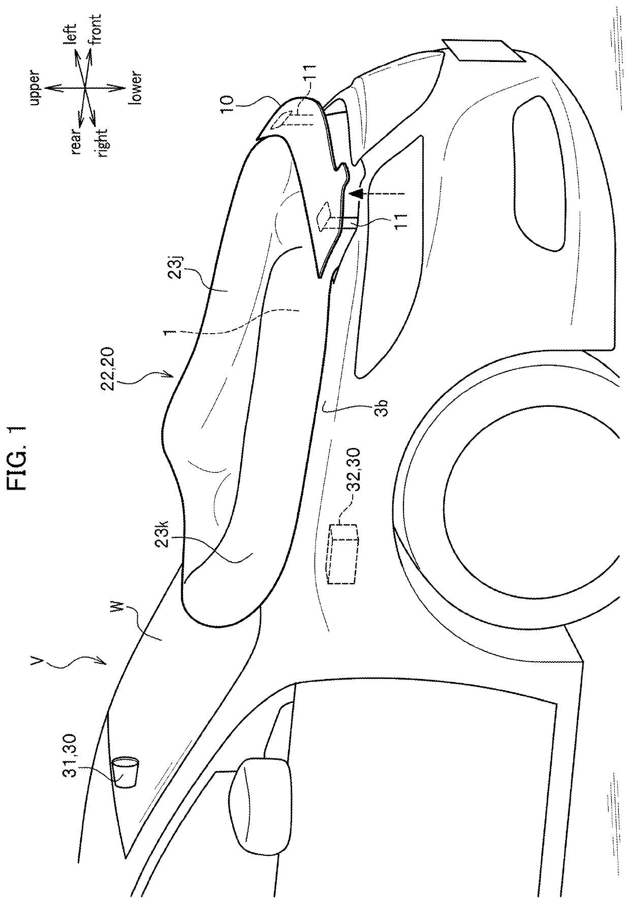
[0020]As illustrated in FIG. 1, an automobile V provided with a vehicle body front structure according to this embodiment includes an enginehood 1 located at a front part of a vehicle body and covering the upper surface of an engine room, and a pop-up hood unit 10 located at the front end portion of the enginehood 1 with its front end portion configured to be lifted above the enginehood 1. In conjunction with an airbag system 20 to be described later, the pop-up hood unit 10 absorbs an impact caused by a collision with a target for protection such as a pedestrian (including a person on a bicycle or the like) (hereinafter simply referred to as the “pedestrian”).
[0021]The pop-up hood unit 10 is made of a metal and obtained by pressing a steel plate, for example. The pop-up hood unit 10 takes on a plate shape that extends in a right-left direction of the vehicle body. The pop-up hood unit 10 is deformable due to an input of an impact in case of a collision with the pedestrian.
[0022]Her...
second embodiment
[0074]A vehicle body front structure of a second embodiment will be described with reference to FIG. 6. This embodiment is different from the first embodiment in that the pop-up hood unit 10 is provided such that an inclination angle of its plate surface is variable relative to a horizontal plane (not illustrated).
[0075]The pop-up hood unit 10 is lifted above the enginehood 1 by a predetermined amount through the lift-up mechanism that includes the not-illustrated driving source configured to drive the support rods 11. In this instance, the pop-up hood unit 10 is bent forward by using a not-illustrated link mechanism or the like. In other words, the plate surface of the pop-up hood unit 10 is turned forward in the process of being lifted and fixed. Here, the bag unit 22 is deployable through the defined opening 5.
[0076]According to this embodiment, the inclination angle of the plate surface of the pop-up hood unit 10 is variable. Hence, the plate surface is set to an inclination ang...
third embodiment
[0078]A vehicle body front structure of a third embodiment will be described with reference to FIG. 7. This embodiment is different from the first and second embodiments in that the pop-up hood unit 10 is integrally provided with a front grill FG.
[0079]The pop-up hood unit 10 is provided continuously and integrally with an upper end portion of the front grill FG. The pop-up hood unit 10 is bent forward while being turned forward together with the front grill FG through the lift-up mechanism that includes the not-illustrated driving source configured to drive the support rods 11, and is thus lifted above the enginehood 1 by a predetermined amount. Then, the plate surface of the pop-up hood unit 10 is settled in the state of facing forward. Here, the bag unit 22 is deployable through the defined opening 5.
[0080]According to this embodiment, the pop-up hood unit 10 is turned and lifted integrally with the front grill FG. Hence, the plate surface faces the colliding pedestrian H and mov...
PUM
 Abstract
Description
Claims
Application Information
 - R&D Engineer
- R&D Manager
- IP Professional
- Industry Leading Data Capabilities
- Powerful AI technology
- Patent DNA Extraction
Browse by: Latest US Patents, China's latest patents, Technical Efficacy Thesaurus, Application Domain, Technology Topic, Popular Technical Reports.
© 2024 PatSnap. All rights reserved.Legal|Privacy policy|Modern Slavery Act Transparency Statement|Sitemap|About US| Contact US: help@patsnap.com