Foot structure for humanoid robot and robot with the same

a humanoid robot and foot structure technology, applied in the field of humanoid robots, can solve the problems of lowering the control stability of the robot, unstable gait of the robot, and disturbance of the robot's dynamic equilibrium, and achieve the effect of constant stiffness, smooth absorption of impact, and reduced high frequency vibration of the foot structure in a high frequency band

Inactive Publication Date: 2005-08-11
SAMSUNG ELECTRONICS CO LTD
View PDF10 Cites 12 Cited by
  • Summary
  • Abstract
  • Description
  • Claims
  • Application Information

AI Technical Summary

Benefits of technology

[0033] The robot of the present invention has a stiffness characteristic identical to that of a human being. Particularly, the robot has a constant stiffness, when receiving an impact load, a stable standing posture, and a smooth contact between a heel and ground.
[0034] Since the robot includes a shock-absorbing and stabilizing mechanism (SASM) capable of providing an additional rotational DOF and translational DOF, the foot structure can properly contact the floor when the robot performs various human-like motions. Consequently, the robot has a stability even on an uneven floor or a floor with small obstacles thereon.
[0035] Also, since the foot structure of the present invention includes a quasi-toe joint, a foot's sole can properly contact the floor while pushing off the floor.
[0036] In addition, sinc

Problems solved by technology

Due to such a shock, the dynamic equilibrium of the robot may be disturbed and an unstable gait of the robot may be caused.
In addition, a vibration of the foot resulted from the shock is transferred to the body of the robot, thereby lowering a control stability of the robot.
Another problem resulted from the unstable interaction between the robot's foot and the ground occurs when the robot passes an area where small obstacles exist on the ground or a surface of the ground is not flat, even though the robot may use a vision system for assessing the surroundings.
In this case, the robot's foot does not adequately step on the ground, which deteriorate

Method used


Image

  • Foot structure for humanoid robot and robot with the same
  • Foot structure for humanoid robot and robot with the same
  • Foot structure for humanoid robot and robot with the same

Examples


Embodiment Construction

[0061] Reference will now be made in detail to a foot structure for a humanoid robot according to an embodiment of the present invention. In the accompanying drawings, like parts are indicated by the same reference numerals.

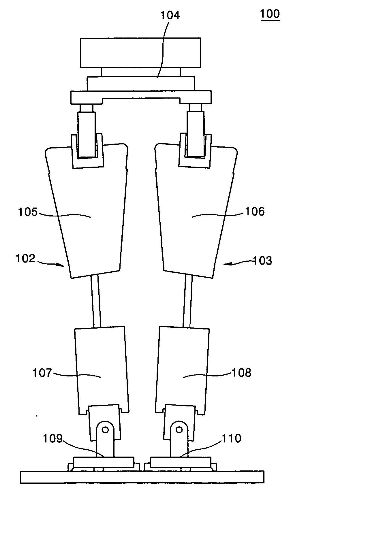
[0062]FIG. 4 is a view depicting a humanoid robot employing a foot structure 100 according to an embodiment of the present invention.

[0063] The humanoid robot 100 includes two legs 102 and 103 and a waist 104.

[0064] Each of the legs 102 and 103 includes thighs 105 and 106, shins 107 and 108, and foot structures 109 and 110, respectively. The legs 102 and 103 and foot structures 109 and 110 are identical to each other and are symmetrically displaced. Accordingly, only the foot structure 110 of the leg 103 will now be described in detail.

[0065]FIG. 5A and FIG. 5B are respectively a perspective view and a cross-sectional view depicting the foot structure.

[0066] As shown in FIGS. 5A and 5B, the foot structure 110 includes a carrier plate 111 for mounting a 6-axi...


PUM

PropertyMeasurementUnit
Diameteraaaaaaaaaa
Shapeaaaaaaaaaa
Stiffnessaaaaaaaaaa

Abstract

Provided is a foot structure for a humanoid robot capable of effectively keeping its balance in a pause state or action. The foot structure includes a support; a plurality of lower structures having an upper member connected to a bottom of the support; a plurality of lower members having a plurality of independent portions each movably connected to the upper member; and a revolute joint for coupling the upper member and the lower member. Since a contact between the foot structure and the floor is smoothly made, a shock is prevented from being transferred to a body of the humanoid robot. Also, a vibration generated when the humanoid robot steps on the floor is eliminated, so that the humanoid robot can pose a stable and smooth gate.

Description

[0001] Priority is claimed to Korean Patent Application No. 2004-7855, filed on Feb. 6, 2004, in the Korean Intellectual Property Office, the disclosure of which is incorporated herein in its entirety by reference. BACKGROUND OF THE INVENTION [0002] 1. Field of the Invention [0003] The present invention relates to a humanoid robot, and more particularly, to a foot structure for a humanoid robot capable of effectively keeping its balance in a pause state and / or action state. [0004] 2. Description of the Related Art [0005] Robots are generally utilized for factory automation and play an important role in non-human environments. Recently, humanoid robot systems are being actively developed because robots capable of performing in a human environment such as offices, homes, or hospitals are desired. Accordingly, some humanoid robots have been developed. [0006] One of most important conditions of a humanoid robot is to guarantee an effective interaction between a foot of the robot and the...

Claims


Application Information

Patent Timeline
IPC IPC(8): B25J13/08B25J5/00B25J19/00
CPCB25J19/0091B25J13/085E06B3/9636E06B3/221
Inventor MASLOV, LEONIDSON, YOUNGKWAK, JOO-YOUNG
Owner SAMSUNG ELECTRONICS CO LTD
Why Eureka
Try Eureka