Spatial and Temporal-based Diffusive Correlation Spectroscopy Systems and Methods

a diffusive correlation and spectroscopy technology, applied in the field of spatial and temporal-based diffusive correlation spectroscopy systems and methods, can solve the problem that conventional dcs systems cannot operate fast enough to detect event-related optical signals

Active Publication Date: 2019-12-26
HI LLC
View PDF0 Cites 31 Cited by
  • Summary
  • Abstract
  • Description
  • Claims
  • Application Information

AI Technical Summary

Problems solved by technology

However, conventional DCS systems do not operate fast enough to detect event-related optical signals caused, for example, by cellular activity, which occurs at a much faster rate than changes in blood flow.

Method used


Image

  • Spatial and Temporal-based Diffusive Correlation Spectroscopy Systems and Methods
  • Spatial and Temporal-based Diffusive Correlation Spectroscopy Systems and Methods
  • Spatial and Temporal-based Diffusive Correlation Spectroscopy Systems and Methods

Examples


Embodiment Construction

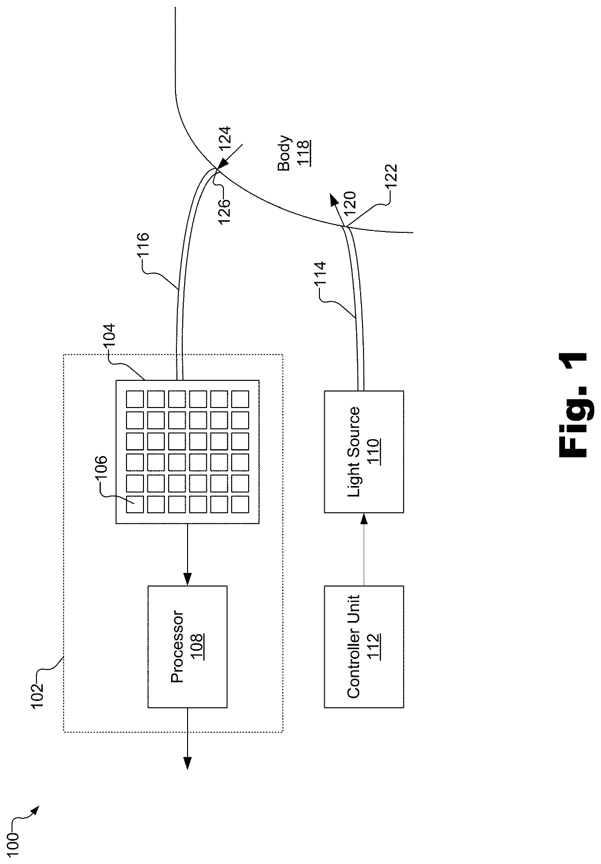
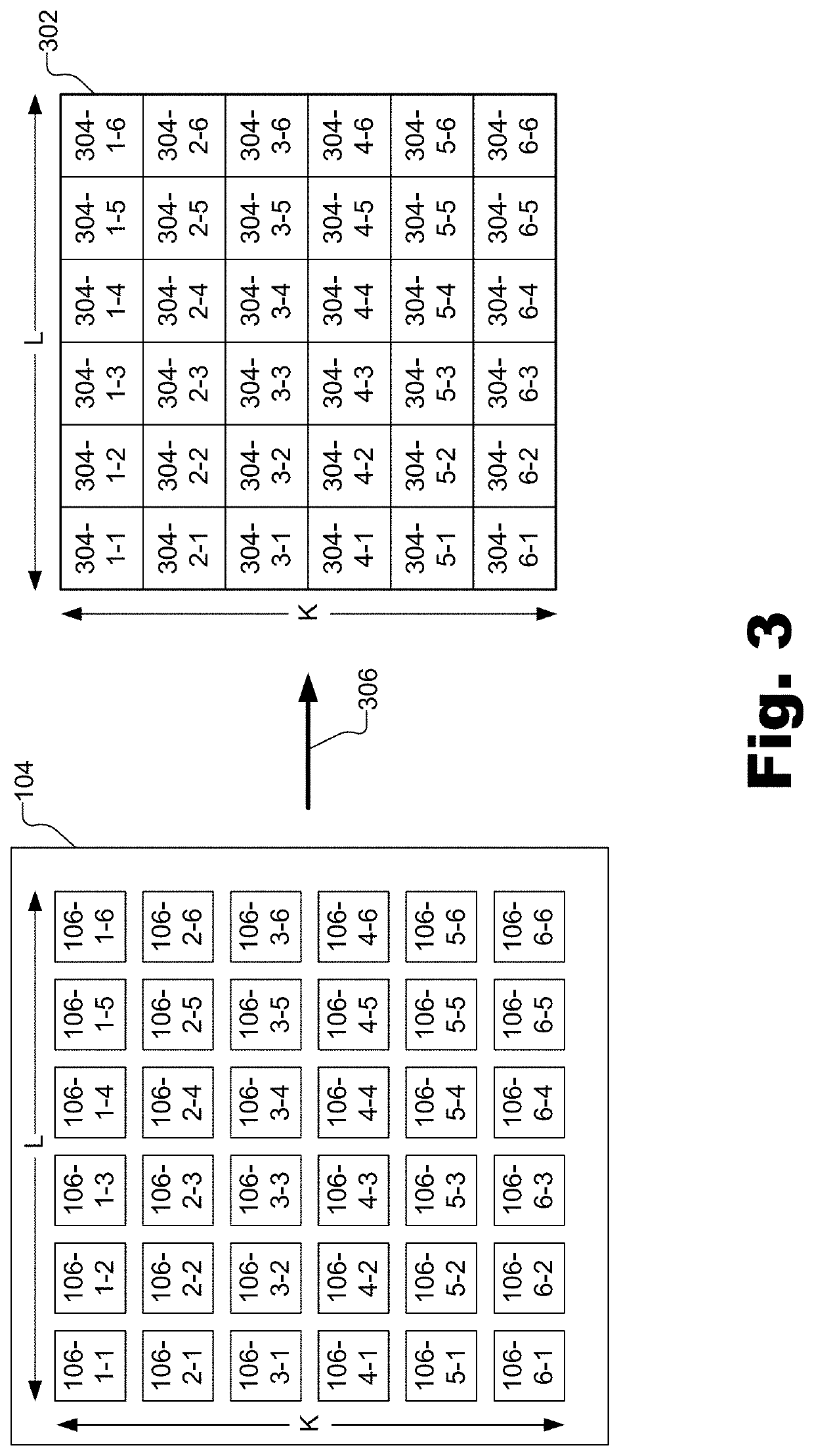
[0020]Spatial and temporal-based DCS systems and methods are described herein. In some examples, as will be described in more detail below, a light source (e.g., a laser diode) generates coherent light that enters a body (e.g., a head of a subject) at an input location. The incident light scatters through many different optical paths within the body. Because of its high coherence, the light emerges from the body with the ability to interfere with itself to produce an interference pattern at one or more output locations. This interference pattern takes the form of a fully developed speckle pattern at the one or more output locations. A DCS system as described herein may determine spatiotemporal correlation measurement values representative of speckle decorrelation (i.e., how speckles within the speckle pattern vary with respect to time and space).

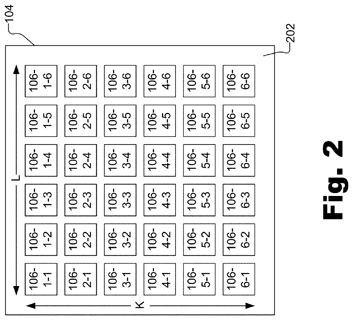
[0021]To this end, the DCS system includes a K by L photodetector array and a processor coupled to an output of the photodetector array. Th...


PUM


Abstract

A system includes an assembly, a pinhole array, and a processor. The assembly includes a K by L photodetector array comprising a plurality of photodetectors and configured to detect light that exits a body at a second location after the light enters the body at a first location different than the second location and scatters within the body, and output a plurality of electronic signals representative of the detected light as a function of time. The pinhole array has a K by L array of pinholes configured to be aligned with the photodetectors and is configured to allow a certain amount of light to be incident upon each of the photodetectors. The processor is configured to generate a correlation map that includes a plurality of spatiotemporal correlation measure values corresponding to the light detected by the photodetector array.

Description

RELATED APPLICATIONS[0001]This application is a continuation application of U.S. patent application Ser. No. 16 / 226,625, filed on Dec. 19, 2018, which claims priority under 35 U.S.C. § 119(e) to U.S. Provisional Patent Application No. 62 / 687,657, filed on Jun. 20, 2018, and to U.S. Provisional Patent Application No. 62 / 717,664, filed on Aug. 10, 2018. These applications are incorporated herein by reference in their respective entireties.BACKGROUND INFORMATION[0002]Detection of brain activity is useful for medical diagnostics, imaging, neuroengineering, brain-computer interfacing, and a variety of other diagnostic and consumer-related applications. For example, cerebral blood flow ensures the delivery of oxygen and needed substrates to tissue, as well as removal of metabolic waste products. Thus, detection and quantification of cerebral blood flow is useful for diagnosis and management of any brain injury or disease associated with ischemia or inadequate vascular autoregulation.[0003...

Claims


Application Information

Patent Timeline
Patent Type & Authority Applications(United States)
IPC IPC(8): A61B5/00A61B5/029A61B5/0476A61B5/026A61B5/0402
CPCA61B5/0075A61B5/4064A61B5/7246A61B5/029A61B5/0261A61B5/0402A61B5/0476A61B5/6814A61B5/0022A61B5/0006A61B2562/046G16H40/67A61B5/291A61B5/318A61B5/369
Inventor HORSTMEYER, ROARKEZHOU, HAOJIANGSHEN, YUECHENGRUAN, HAOWEN
Owner HI LLC
Why Eureka
Try Eureka