Interbody Inserter

Inactive Publication Date: 2019-12-26
NEXUS SPINE L L C
View PDF0 Cites 6 Cited by
  • Summary
  • Abstract
  • Description
  • Claims
  • Application Information

AI Technical Summary

Benefits of technology

[0012]Certain implementations of the invention provide a surgical implant insertion system. The surgical implant insertion system includes a cervical interbody implant and an implant inserter. The cervical interbody implant includes an inserter implant interface having a narrow external opening at a surface of the cervical interbody implant and a broader internal opening that is broader than the narrow external opening and that is in communication with the narrow external opening. The implant inserter includes a handle and an inserter shaft fixedly attached to and extending from a distal end of the handle. The implant inserter also includes a pair of flexible tabs extending from a distal end of the inserter shaft, the flexible tabs being separated by an inter-tab space, the flexible tabs having laterally extending

Problems solved by technology

One of the difficulties associated with placing certain surgical implants is the difficulty of surgical access.
In many instances, surgical access is limited, either by anatomy or by surgical choice to limit tissue damage and to facilitate healing.
As a particular example, it can be difficult to place spinal interbody implants, particularly those used for cervical portions of the spine.
As a result, it often becomes difficult to properly place an interbody implant at the exact desired location.
When an implant is not properly placed, the de

Method used


Image

  • Interbody Inserter
  • Interbody Inserter
  • Interbody Inserter

Examples


Example

[0025]A description of embodiments of the present invention will now be given with reference to the Figures. It is expected that the present invention may take many other forms and shapes, hence the following disclosure is intended to be illustrative and not limiting, and the scope of the invention should be determined by reference to the appended claims.

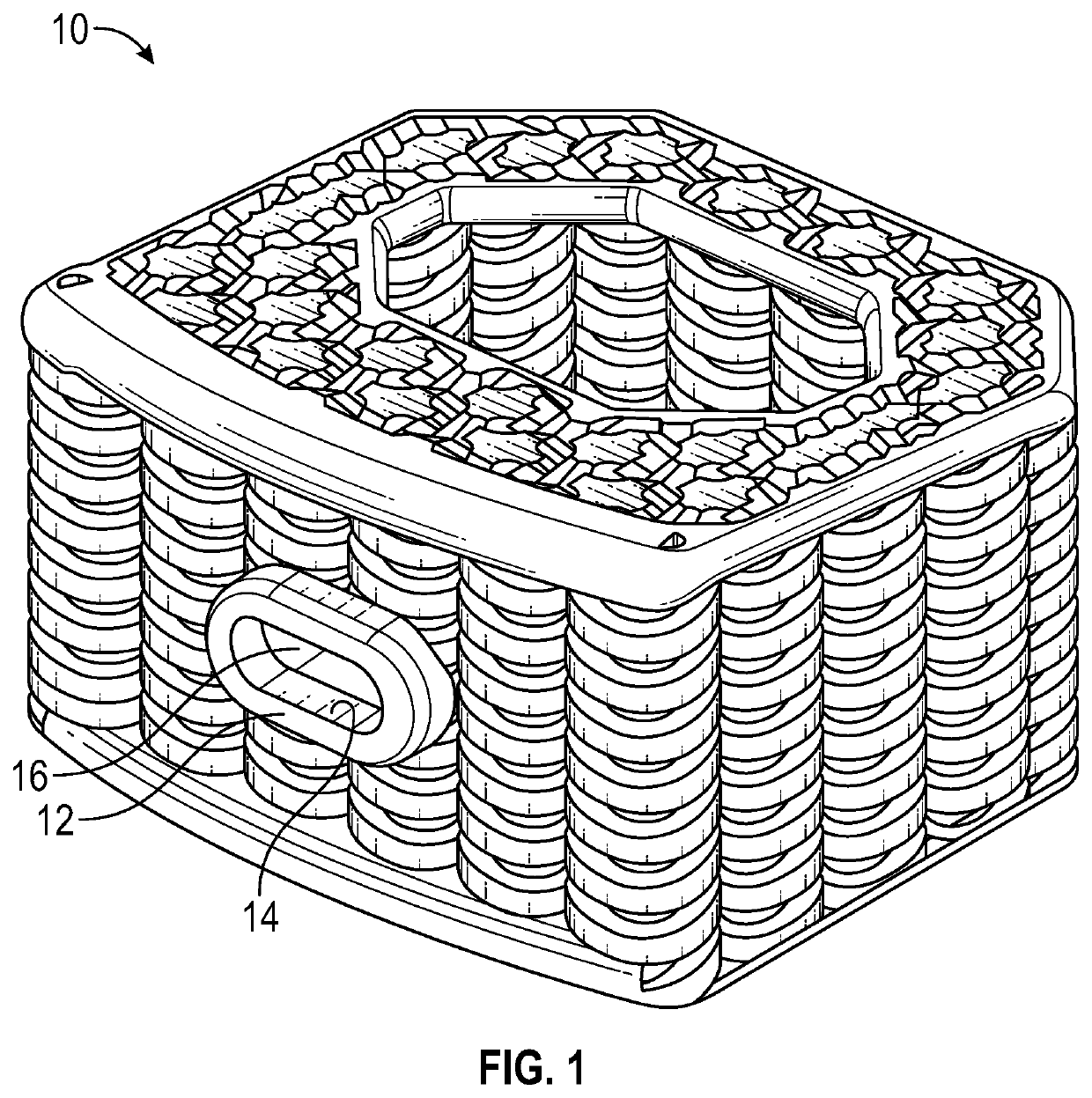
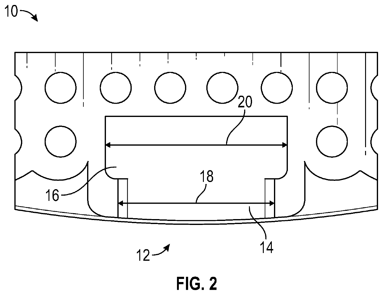
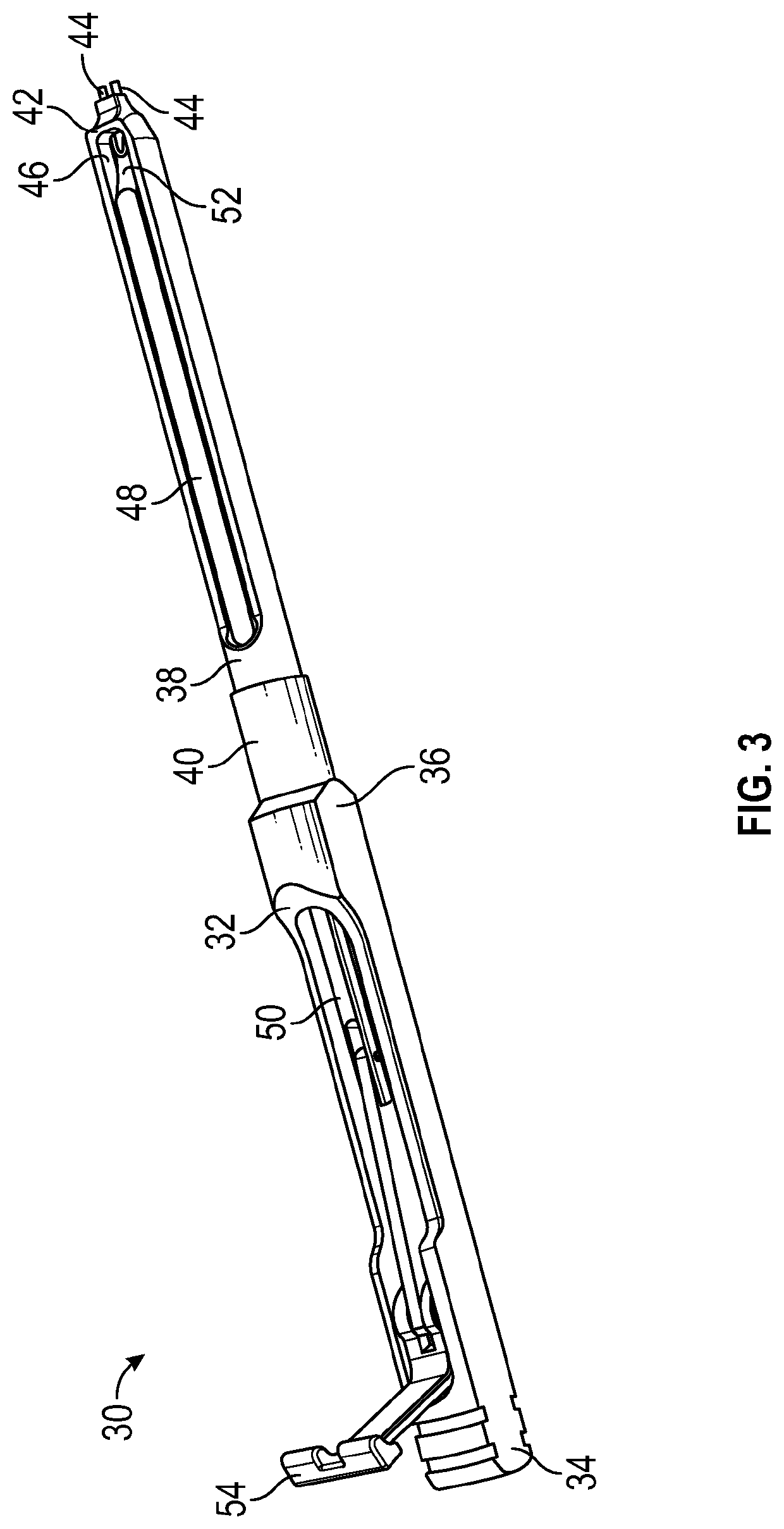
[0026]Embodiments of the invention provide surgical implant systems and methods for their use. In particular, embodiments of the invention provide surgical implants and implant inserters and methods for using such in surgical implantation procedures. Particular embodiments of the invention provide interbody spacer implants and accompanying interbody spacer inserters and methods for using such in spinal fusion procedures. Further particular embodiments of the invention provide cervical interbody spacer implants and accompanying interbody spacer inserters and methods for using such in spinal fusion procedures. Embodiments of the inven...


PUM

PropertyMeasurementUnit
Flexibilityaaaaaaaaaa

Abstract

An implant inserter is adapted to secure and facilitate insertion of a surgical implant. The implant has an inserter attachment interface having a narrow external opening at a surface thereof and a broader internal opening. The implant inserter includes a handle and an inserter shaft. The implant inserter also includes a pair of flexible tabs extending from a distal end of the inserter shaft with laterally extending protrusions adapted to extend into the broader internal opening and an expansion shaft adapted to selectively extend between the flexible tabs whereby the expansion shaft prevents flexion of the flexible tabs such that the laterally extending protrusions secure the surgical implant, and whereby when the expansion shaft does not extend between the flexible tabs, the flexible tabs can be flexed inwardly to cause the laterally extending protrusions to have a narrower profile that is able to be passed through the narrow external opening.

Description

CROSS-REFERENCE TO RELATED APPLICATIONS[0001]This application claims the benefit of U.S. Provisional Application No. 62 / 689,707, filed Jun. 25, 2018.BACKGROUND OF THE INVENTION1. Field of the Invention[0002]The present invention relates to medical implants, and more particularly to systems and methods for inserting implants such as spinal interbody implants.2. Background and Related Art[0003]One of the difficulties associated with placing certain surgical implants is the difficulty of surgical access. In many instances, surgical access is limited, either by anatomy or by surgical choice to limit tissue damage and to facilitate healing. As a particular example, it can be difficult to place spinal interbody implants, particularly those used for cervical portions of the spine. In such surgeries, access to the interbody space is typically achieved anteriorly, requiring displacement of other body structures. As a result, it often becomes difficult to properly place an interbody implant a...

Claims


Application Information

Patent Timeline
IPC IPC(8): A61F2/46A61F2/44
CPCA61F2/4611A61F2/447A61F2002/4475A61F2002/30504A61F2002/4627A61F2002/30143A61F2002/4623A61F2002/30268A61F2/442A61F2002/30426A61F2002/30563A61F2002/30566A61F2002/30568A61F2002/30593A61F2002/30772A61F2002/30777A61F2002/30784A61F2002/3092A61F2002/3093A61F2002/30962A61F2002/30985A61F2002/4495A61F2/4603A61F2002/30261A61F2002/305
Inventor HARRIS, JEFFHALVERSON, PETERHAWKES, DAVID
Owner NEXUS SPINE L L C
Why Eureka
Try Eureka