Embedded optical ring communication network for aircraft

a technology of optical ring and communication network, which is applied in the direction of fiber transmission, multimode transmission, transmission, etc., can solve the problems of increased fuel consumption during flight, complex installation and maintenance of cabling, and high cost of cabling, so as to improve the security of data transmission, avoid modal dispersion, and increase the number of equipment

Active Publication Date: 2019-12-26
SAFRAN ELECTRICAL & POWER
View PDF0 Cites 0 Cited by
  • Summary
  • Abstract
  • Description
  • Claims
  • Application Information

AI Technical Summary

Benefits of technology

[0017]An optical communication network according to the invention therefore allows a communication between different equipment at an increased flow (up to several tens of Gb / second over more than one hundred metres): the multiplexing by propagation modes allows being added to the multiplexing commonly used (in particular, wavelength multiplexing and time multiplexing) in so order to increase the number of equipment which can communicate simultaneously over the network. Furthermore, multiplexing by mode allows, by controlling injection and propagation of the modes of the optical signals, to avoid the modal dispersion.
[0018]The separators and the prism of the distribution boxes are passive components, which allow transmitting optical signals without losing the modes of the optical signal transmitted. The separators allow forming, from an optical signal received, and thanks to the passive optical elements, two identical optical signals which are directed to the different portions of the prism. By reflection or refraction, the prism directs a first of these two optical signals towards a first of the other separators and a second of these two signals to a second separator. Likewise, by inverse functioning, each separator receives two optical signals coming from the two other separators, thus allowing a bidirectional functioning of the transmission between each separator, two-by-two.
[0019]The passive functioning of the distribution boxes also allows them to function without the presence of a multiplexer / demultiplexer connected to one of the separators. In this case, the distribution box behaves like a socket in the network, transmitting the optical signals from a nearby distribution box to the following distribution box in the ring, and available to be able to connect new equipment to the network. Thus, the distribution boxes can be distributed in the infrastructure, wherein the network is deployed, for example an aircraft, for new equipment to be added in the future. Likewise, when an item of equipment or a set of equipment must be removed from the network, the associated multiplexer / demultiplexer can be disconnected from the distribution box, without requiring reconfiguration of the network for the correct functioning thereof.
[0020]Multiplexing by mode also allows improving the security of the data transmission, as the operation of separating the modes (demultiplexing) can be carried out only by modal demultiplexers: an interception of data at the level of the optical fibers, for example by stripping and curving this optical fiber, will not allow obtaining a readable optical signal.

Problems solved by technology

In order to connect equipment of an aircraft together for communication purposes, the aircraft are equipped with different cabling forming a network, whose installation and maintenance can be complex.
Furthermore, this cabling presents a high cost, on the one hand, in terms of cable prices, but also in terms of weight, leading to an increase in fuel consumption during the flight.
This type of copper cable network has several disadvantages: the metal cables cause problems of electromagnetic disturbances (electromagnetic compatibility, current induction, etc.), the network is hardly adaptable to the modifications (adding new equipment, for example), the network has a flow limited to a few tens of Mb / sec (mainly due to the determining aspect of the TCP protocol), and the weight of the cables is significant (around 32 kg / km, an aeroplane can comprise, for example, several hundred kilometres of cables).
To all these disadvantages is furthermore added a high maintenance and modification cost.
However, the obtained network r does not provide for a great adaptability.

Method used


Image

  • Embedded optical ring communication network for aircraft
  • Embedded optical ring communication network for aircraft

Examples


Embodiment Construction

[0037]The following embodiments are examples. Although the description refers to one or more embodiments, this does not necessarily mean that each reference concerns the same embodiment, or that the characteristics are only applied to one single embodiment. Single characteristics of different embodiments can also be combined to provide other embodiments. In the so figures, the scales and proportions are not strictly respected for purposes of illustration and clarity.

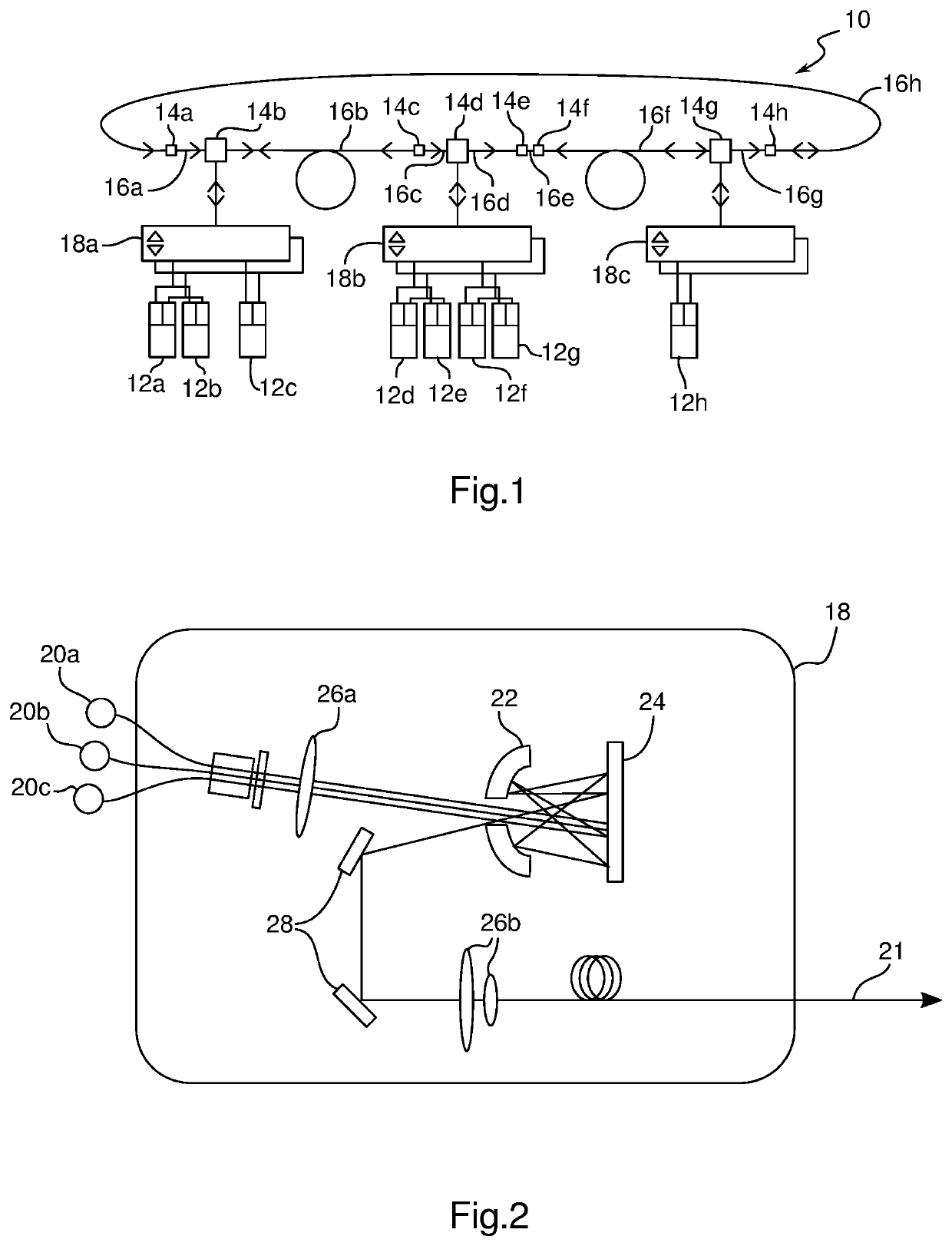
[0038]FIG. 1 schematically represents an optical ring communication network 10 according to an embodiment of the invention, embedded for example in an aircraft. The optical network 10 is intended to enable the transmission of computerised data between equipment 12a-12h. For this purpose, the communication network comprises an assembly of distribution boxes 14a-14h, each connected directly to two other distribution boxes by multimode and bidirectional optical fibers 16a-16h so as to form a ring. As visible in particular b...


PUM


Abstract

The invention concerns an embedded optical ring communication network (10) suitable for transmitting data between equipment (12a-12h), characterised in that it comprises an assembly of distribution boxes (14a-14h) each connected to two other distribution boxes (14a-14h) by multimode bidirectional optical fibres (16a-16h) so as to form a ring, suitable for also being connected to a multiplexer/demultiplexer (18a, 18b, 18c) by multimode bidirectional optical fibres, and in that each optical fibre (16a-16h) is suitable for transporting optical signals of at least three different modes (32, 32, 34).

Description

1. TECHNICAL FIELD OF THE INVENTION[0001]The invention concerns an embedded optical network of the ring network type. In particular, the invention concerns an optical communication network which can be embedded in an aircraft in order to allow aircraft equipment communicating together.2. TECHNOLOGICAL BACKGROUND[0002]In order to connect equipment of an aircraft together for communication purposes, the aircraft are equipped with different cabling forming a network, whose installation and maintenance can be complex. Furthermore, this cabling presents a high cost, on the one hand, in terms of cable prices, but also in terms of weight, leading to an increase in fuel consumption during the flight.[0003]In addition, the current networks generally use copper cables forming a star and ring network mixture, of the AFDX “Switched Ethernet” type. The cables use a copper support of two twisted and redundant pairs.[0004]This type of copper cable network has several disadvantages: the metal cable...

Claims


Application Information

Patent Timeline
Patent Type & Authority Applications(United States)
IPC IPC(8): H04B10/2581H04B10/275H04B10/25H04J14/04
CPCH04B10/2503H04J14/04H04B10/2581H04B10/275H04B10/2589
Inventor GARCIA, JEAN-PIERRELE GALL, SEBASTIEN
Owner SAFRAN ELECTRICAL & POWER
Why Eureka
Try Eureka