Fixing device and image forming apparatus

a fixing device and image forming technology, applied in the field of electrographic image forming apparatus, can solve the problems of temperature gap between the heating section and gloss unevenness in the fixed image, and achieve the effect of reducing gloss unevenness of the printing imag

Active Publication Date: 2020-01-02
OKI ELECTRIC IND CO LTD
View PDF0 Cites 3 Cited by
  • Summary
  • Abstract
  • Description
  • Claims
  • Application Information

AI Technical Summary

Benefits of technology

[0008]With such a configuration, even when the heater of the fixing device has divided heating sections, a temperature gap on a surface of the endless belt can be reduced, and therefore gloss unevenness of a printing image can be reduced.

Problems solved by technology

However, in the heater, a temperature gap occurs between the heating section and a border section between the adjacent heating sections.
This causes a variation in temperature of a surface of the belt (i.e., a surface contacting a developer), and thus gloss unevenness occurs in a fixed image.

Method used


Image

  • Fixing device and image forming apparatus
  • Fixing device and image forming apparatus
  • Fixing device and image forming apparatus

Examples


embodiment 1

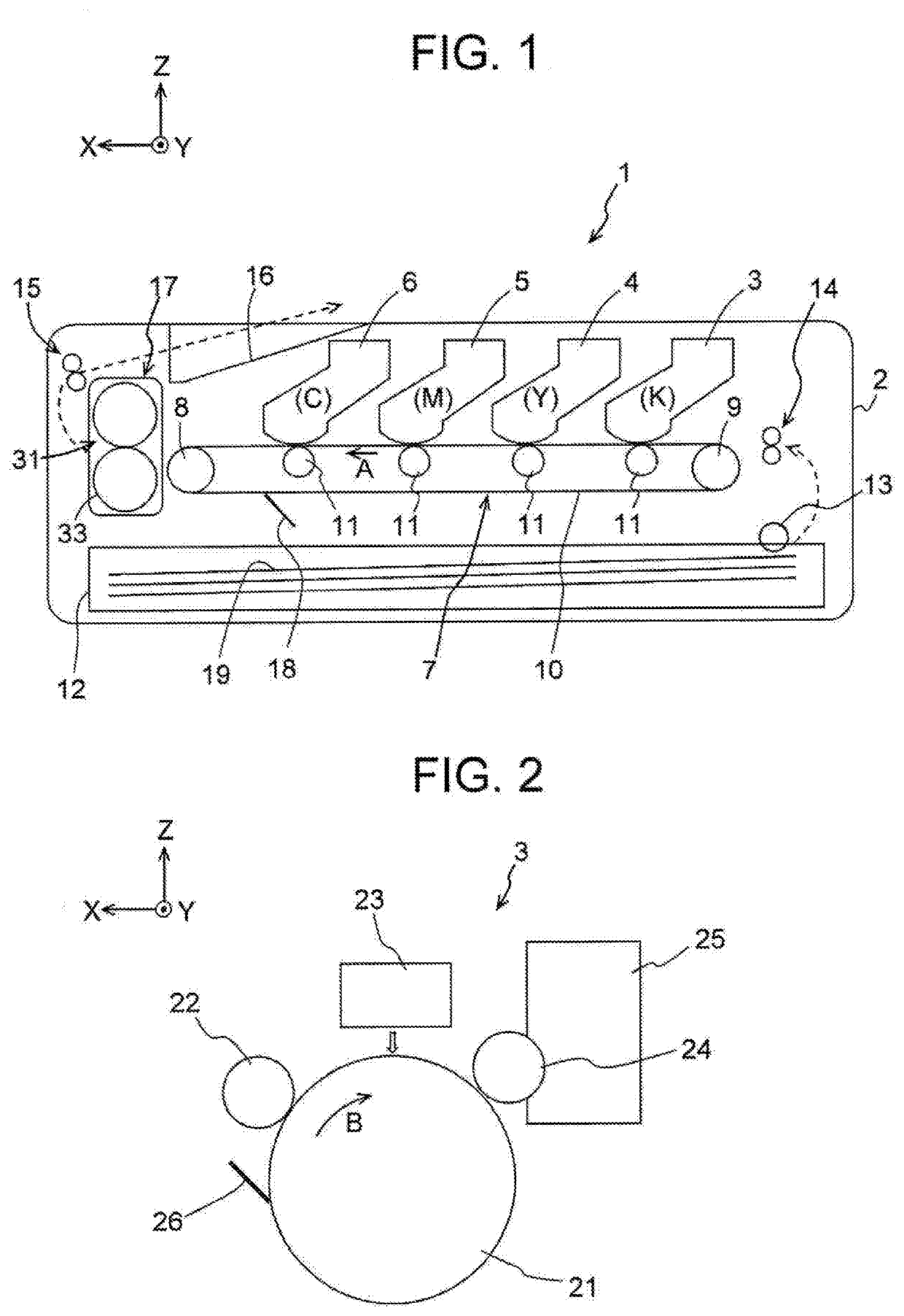
[0027]FIG. 1 is a diagram illustrating a configuration of a main part of an image forming apparatus 1 including a fixing device 17 according to Embodiment 1 of the present invention. FIG. 2 is a diagram illustrating a configuration of a main part of an image forming unit 3.

[0028]As shown in FIG. 1, the image forming apparatus 1 includes a sheet feed cassette 12, a hopping roller 13, a pair of registration rollers 14, and a housing 2 accommodating these components. The sheet feed cassette 12 stores recording sheets 19 as recording media. The hopping roller 13 takes the recording sheet 19 out of the sheet feed cassette 12. The pair of registration rollers 14 correct a skew of the recording sheet 19 and convey the recording sheet 19 to an image forming section. In the housing 2, image forming units 3, 4, 5 and 6 are arranged in this order from an upstream side along a conveyance path of the recording sheet 19 conveyed in a direction indicated by an arrow A. The image forming units 3 th...


PUM


Abstract

A fixing device includes an endless belt. A heat supply part is disposed inside the belt, contacts an inner circumferential surface thereof, and supplies heat thereto. A pressure member contacts an outer circumferential surface of the belt to form a nip portion, and conveys a recording medium while nipping the recording medium together with the belt. The heat supply part includes a heater having a plurality of heating sections arranged in a widthwise direction of the belt, and a thermal diffusion member extending in the widthwise direction between the heater and the belt. One surface of the thermal diffusion member contacts the inner circumferential surface of the belt, and the other surface contacts the heating sections. A plate thickness t (mm) between the surfaces of the thermal diffusion member, and a thermal diffusivity D (mm2/s) of the thermal diffusion member satisfy the relationship: t×D≥6.7.

Description

BACKGROUND OF THE INVENTION1. Field of the Invention[0001]The present invention relates to an electrophotographic image forming apparatus and more particularly relates to a thermal fixing device including a fixing belt.2. Description of the Related Art[0002]A general fixing device includes a fixing belt and a heater for heating the fixing belt. The heater has a plurality of divided heating sections arranged in a widthwise direction of the fixing belt. One or more of the heating sections corresponding to a printing image area that varies depending on a size of a printing medium is caused to generate heat (see, for example, Patent Reference 1).[0003]Patent Reference 1: Japanese Patent Application Publication No. 2016-65915 (page 7, FIG. 5)SUMMARY OF THE INVENTION[0004]However, in the heater, a temperature gap occurs between the heating section and a border section between the adjacent heating sections. This causes a variation in temperature of a surface of the belt (i.e., a surface co...

Claims


Application Information

Patent Timeline
Patent Type & Authority Applications(United States)
IPC IPC(8): G03G15/20
CPCG03G15/2057G03G2215/2025G03G15/2042G03G15/2053G03G2215/2035
Inventor TAKAZAWA, TAKAYUKI
Owner OKI ELECTRIC IND CO LTD
Why Eureka
Try Eureka