Cross dichroic prism, image display module, and image display device
a technology image display module, which is applied in the field of cross dichroic prism, image display module, image display device, etc., can solve the problems of deteriorating display device quality, dielectric multilayer film breakage, and increased stress on the dielectric multilayer film
- Summary
- Abstract
- Description
- Claims
- Application Information
AI Technical Summary
Benefits of technology
Problems solved by technology
Method used
Image
Examples
first exemplary embodiment
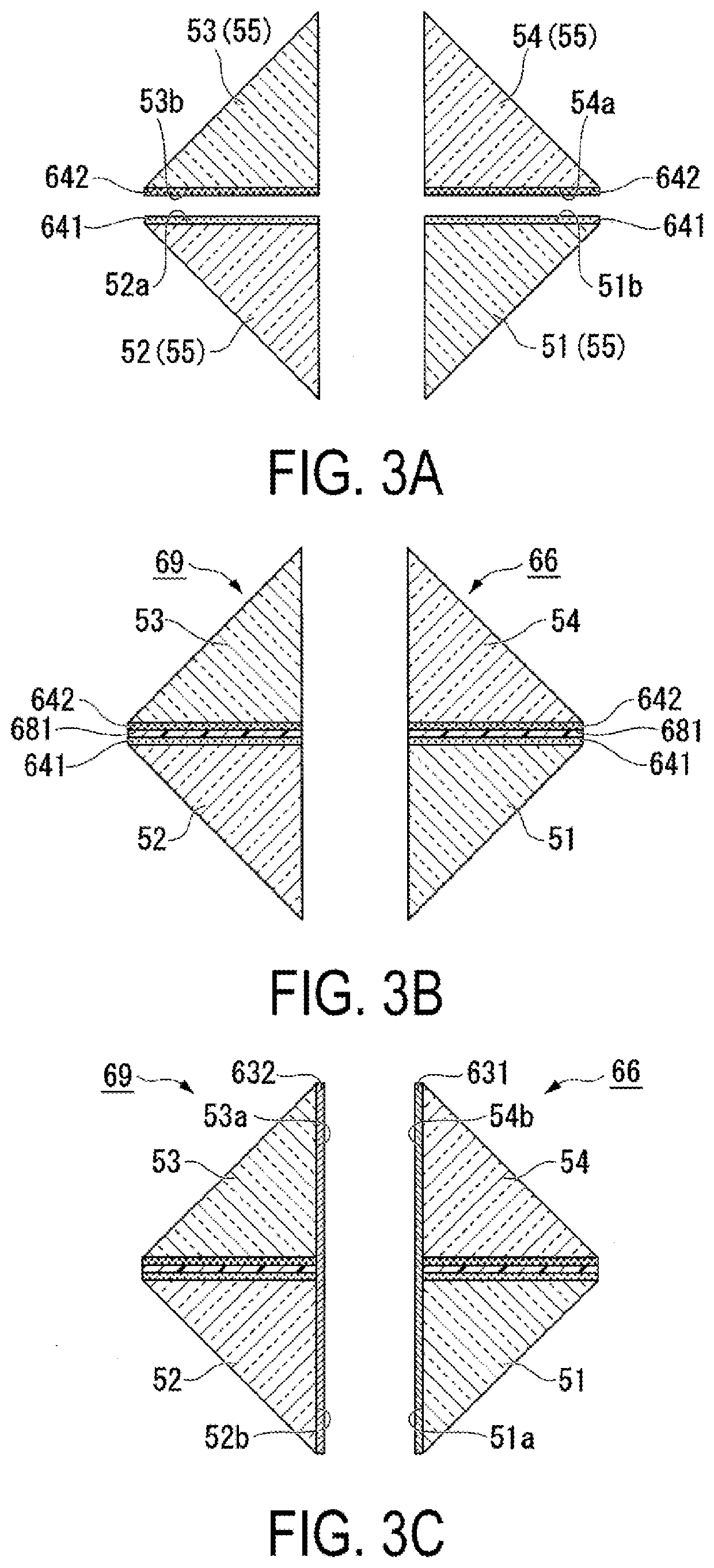
[0033]Below, a first exemplary embodiment according to the present disclosure will be described with reference to FIGS. 1, 2, and 3A to 3C.
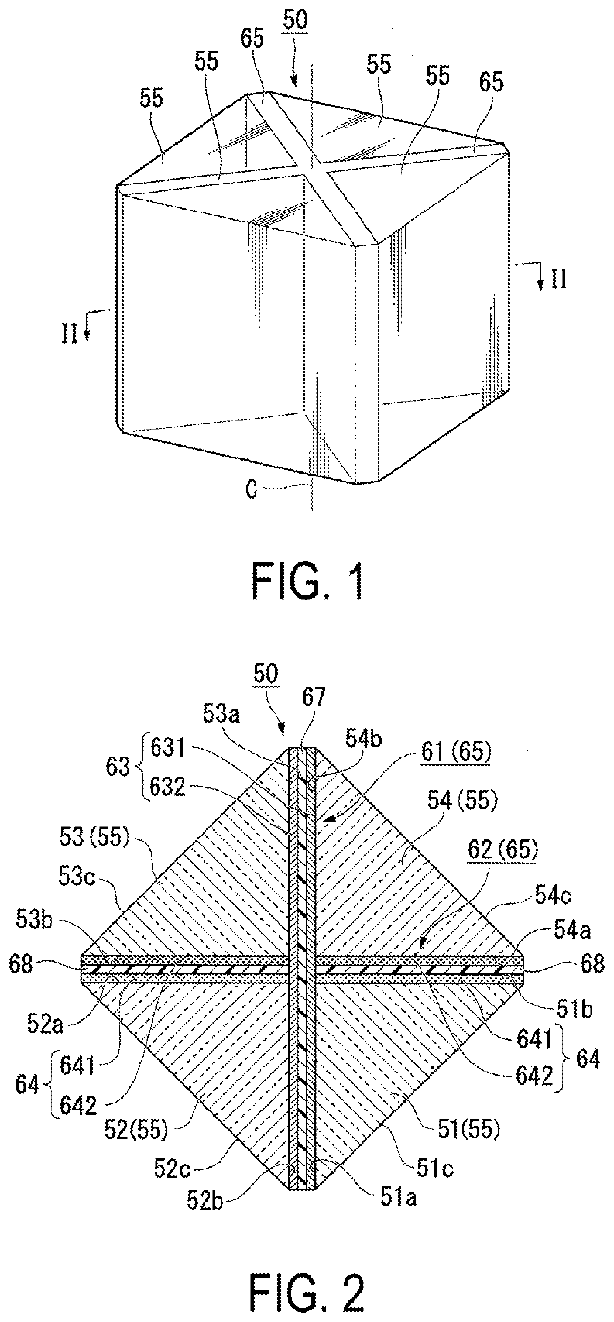
[0034]FIG. 1 is a perspective view illustrating a cross dichroic prism 50 according to the first exemplary embodiment. FIG. 2 is a cross-sectional view taken along the line II-II in FIG. 1.
[0035]Note that, in the drawings, the dimensions of some components may be scaled differently for the ease of understanding for the components.
[0036]The cross dichroic prism 50 according to the first exemplary embodiment is used, for example, to synthesize a plurality of imaging lights from a plurality of image display panels such as organic EL panels that emit an imaging light that does not have a polarization property.
[0037]As illustrated in FIGS. 1 and 2, the cross dichroic prism 50 includes four prisms 55 and two dichroic mirrors 65.
[0038]For the purpose of explanation, in FIG. 2, a prism illustrated in the lower right is referred to as a first prism 51. Af...
second exemplary embodiment
[0085]Below, a second exemplary embodiment according to the present disclosure will be described with reference to FIG. 4.
[0086]The basic configuration of a cross dichroic prism according to the second exemplary embodiment is similar to that of the first exemplary embodiment, and the film thickness of an adhesive layer differs from that in the first exemplary embodiment. Thus, the entire description of the cross dichroic prism will not be repeated.
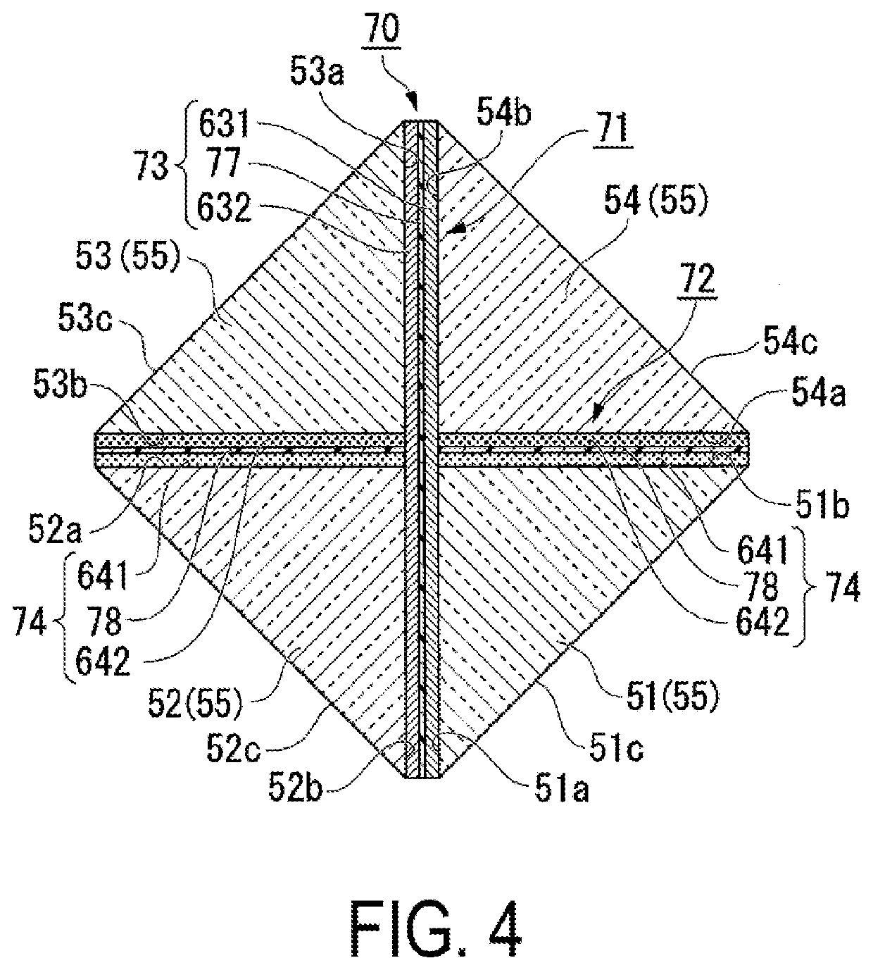
[0087]FIG. 4 is a cross-sectional view illustrating a cross dichroic prism according to the second exemplary embodiment. As in FIG. 2, the drawing of FIG. 4 corresponds to a cross-sectional view at the line II-II in FIG. 1.
[0088]In FIG. 4, the constituent elements common to those in FIG. 2 are denoted with the same reference characters, and the description thereof will not be repeated.
[0089]As illustrated in FIG. 4, a cross dichroic prism 70 according to the second exemplary embodiment includes the four prisms 55 and two dichroic mirrors 7...
third exemplary embodiment
[0094]Below, a third exemplary embodiment according to the present disclosure will be described with reference to the drawings.
[0095]The cross dichroic prism described in the first exemplary embodiment and the second exemplary embodiment is used in a display device described below.
[0096]FIG. 5 is an explanatory diagram illustrating a head-mounted display device 1000 according to the third exemplary embodiment. FIG. 6 is a perspective view schematically illustrating a configuration of an optical system of virtual image display units 1010 illustrated in FIG. 5. FIG. 7 is an explanatory diagram illustrating optical paths of the optical system illustrated in FIG. 6.
[0097]As illustrated in FIG. 5, the head-mounted display device 1000 (image display device) is configured as a see-through type eyeglass display and includes a frame 1110 provided with left and right temples 1111 and 1112. In the head-mounted display device 1000, the virtual image display units 1010 are supported by the frame...
PUM
| Property | Measurement | Unit |
|---|---|---|
| thickness | aaaaa | aaaaa |
| thickness | aaaaa | aaaaa |
| angle | aaaaa | aaaaa |
Abstract
Description
Claims
Application Information
 - R&D
- Intellectual Property
- Life Sciences
- Materials
- Tech Scout
- Unparalleled Data Quality
- Higher Quality Content
- 60% Fewer Hallucinations
Browse by: Latest US Patents, China's latest patents, Technical Efficacy Thesaurus, Application Domain, Technology Topic, Popular Technical Reports.
© 2025 PatSnap. All rights reserved.Legal|Privacy policy|Modern Slavery Act Transparency Statement|Sitemap|About US| Contact US: help@patsnap.com


